This project was very straightforward, and broke down into three steps.1
1) Milling the board
2) Soldering the components
3) Testing and Programming
Milling the board
I decided to produce the most basic board for simplicity.
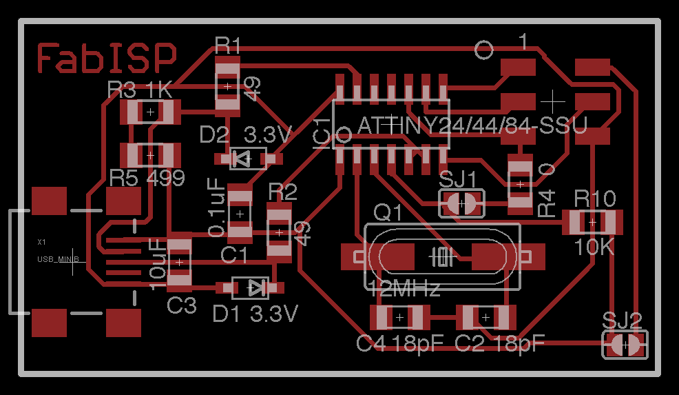
The board design
Running the mill was more difficult than I anticipated. Setting it up using fab modules was simple. The only snag I hit here was ensuring that the mill tip was sharp enough to get a good cut. My first few few passes, the tip was close to the end of it’s useful life, resulting in a lot of burrs, which required a lot of washing to get them clean enough for work.
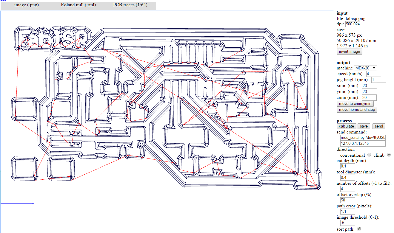
Fab modules imput
Soldering the Components
I had some experience with soldering pass through boards before coming into the class. Nevertheless, getting to the point where I was producing joints of reasonable quality took two boards. Once I started to add flux to the board the work got a lot easier. Definitely the most difficult part was soldering the mini USB components to the board.
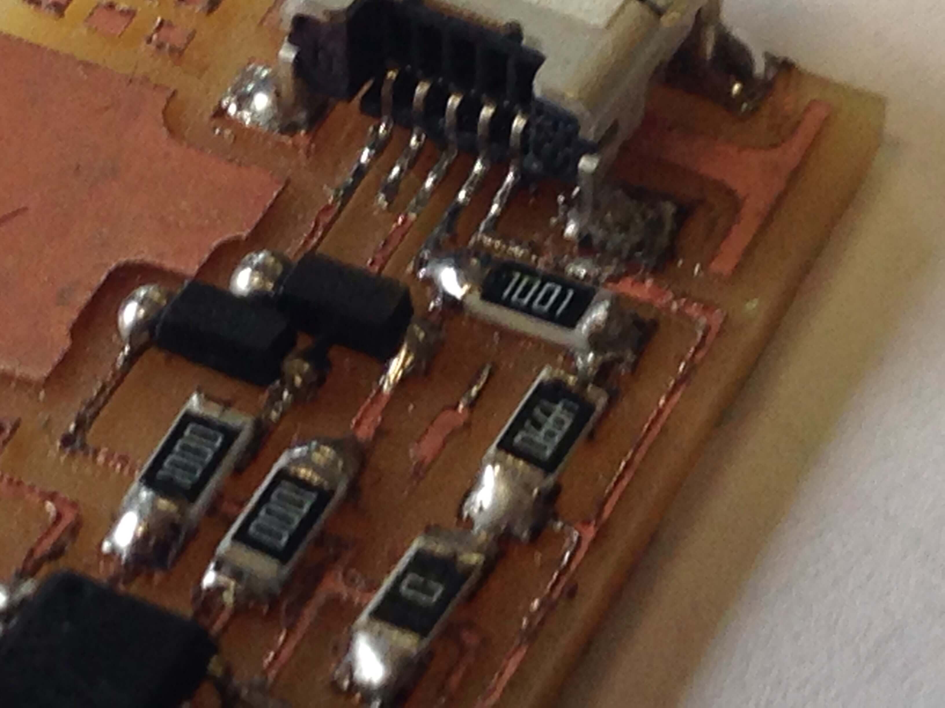
Biggest Struggle
In the above picture you can see two things. The quality of the soldering, which is subpar vs what experienced joints look like and the burring on the material. Thankfully it worked and I was glad for that.
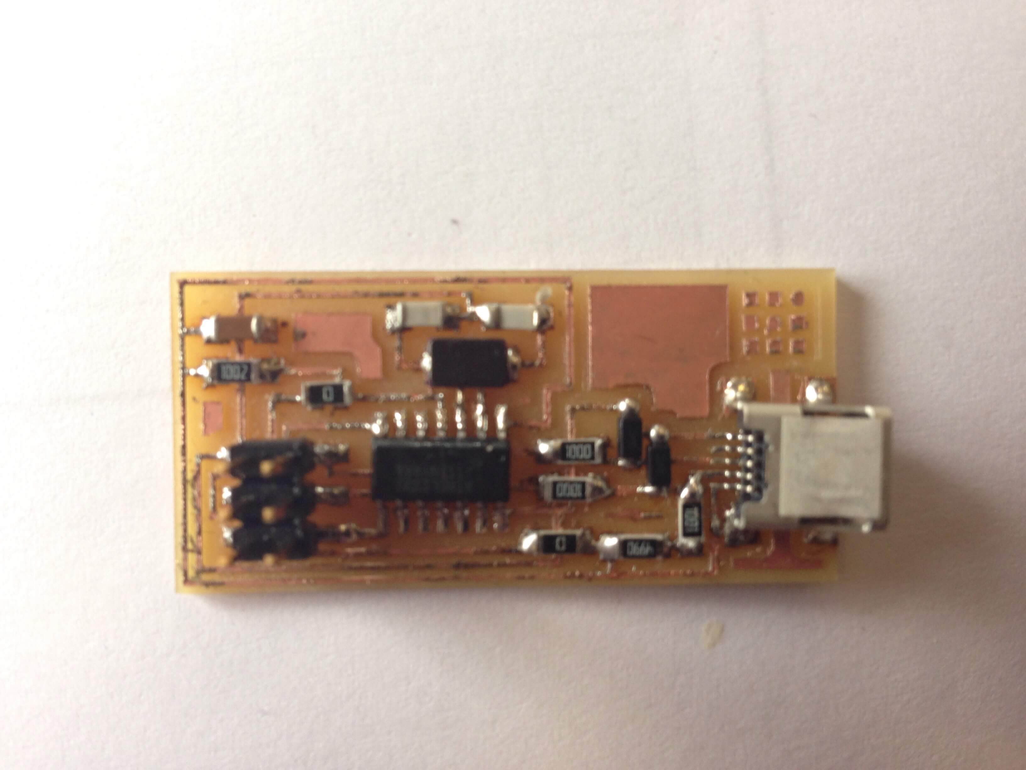
Finished Product
Programming
Programming
As I mentioned above, the first board I plugged in got the red light on the programmer. I knew the board was likely going to be bad because of the burring and I wanted more practice with soldering so I decided to make another board. When I plugged that one in I got a green light and then executed the code to program it.