This week I challenged myself to make a usable desk with less than $10 in material. I wanted to learn three things from doing this. First, I wanted to draw in Solidworks. It’s the go-to program for mechanical modeling and I thought a working knowledge would be helpful. Second, I wanted the design to be parametric. This would allow me to change the size of the desk without a lot of rework and make adjustments for material. Finally, I wanted to figure out how to convert a 3D design down to the 2D that would be needed for CNC.
The Idea
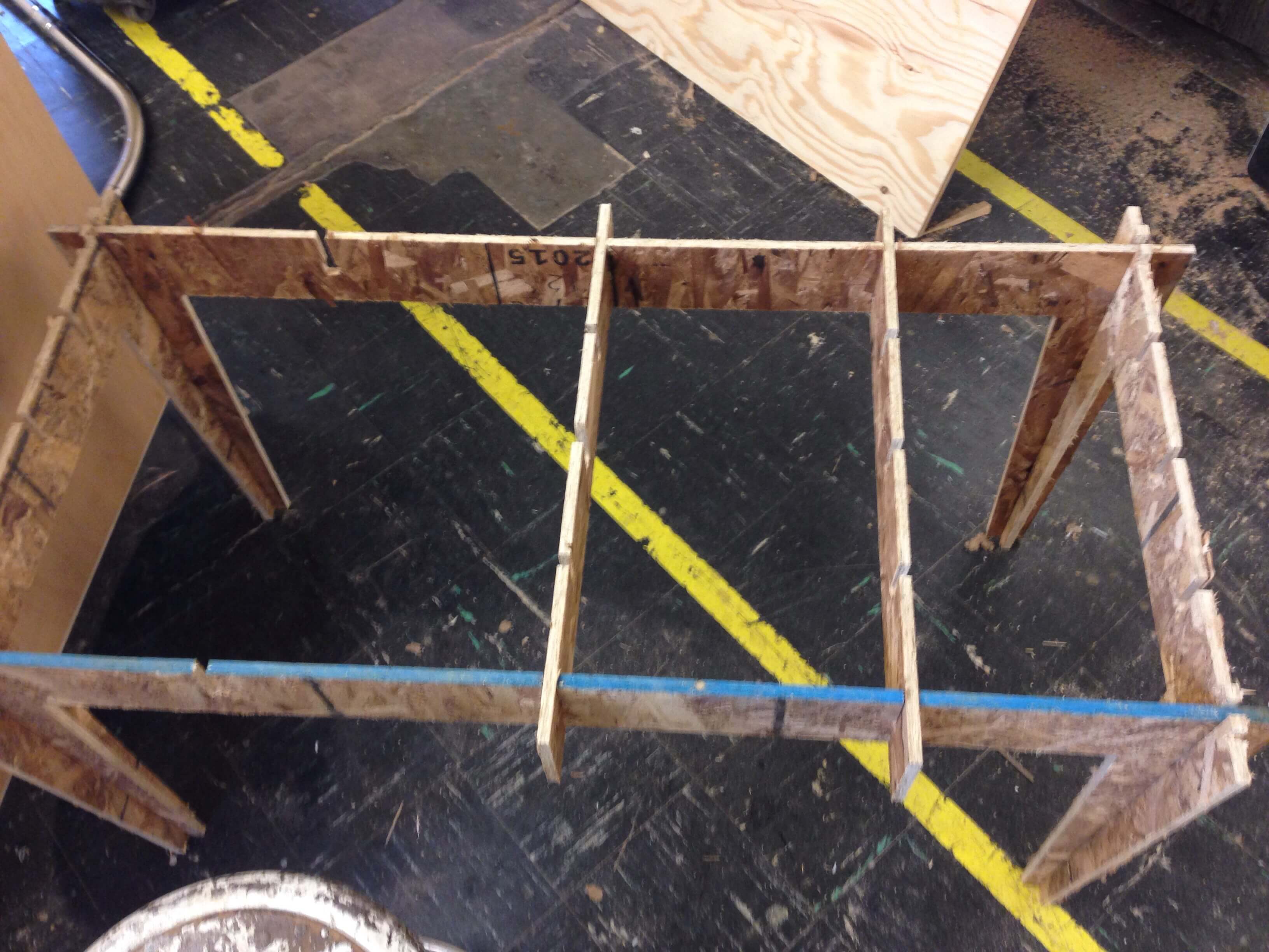
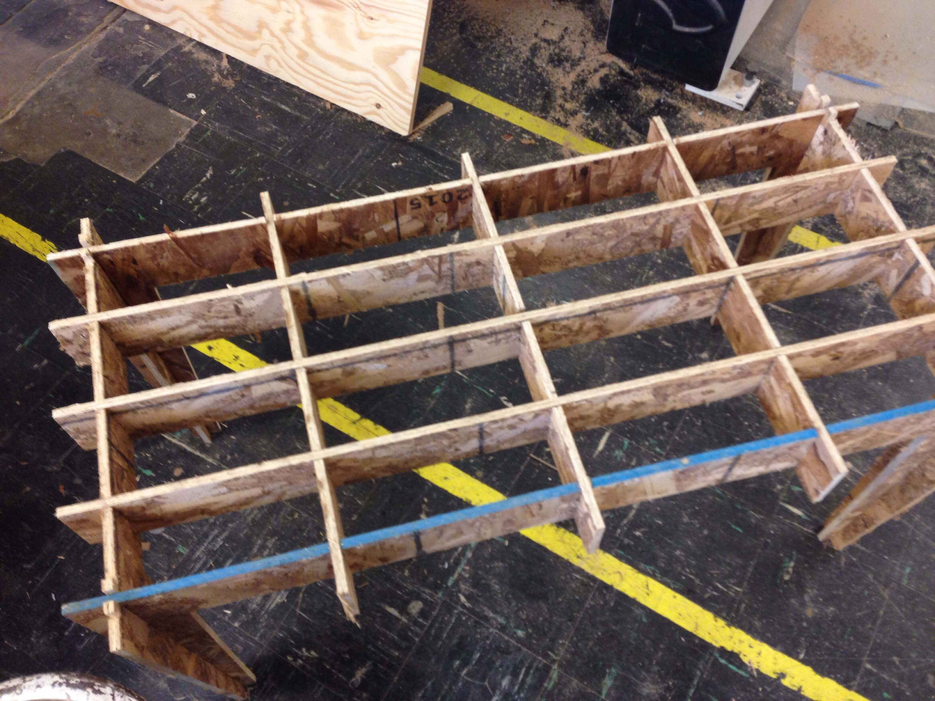
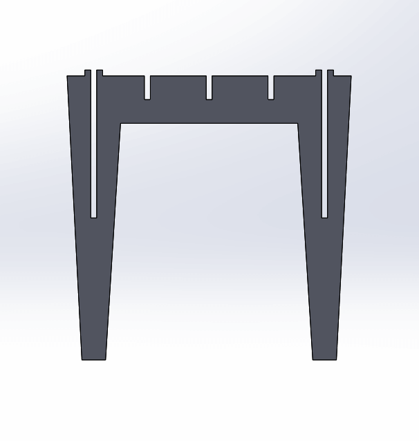
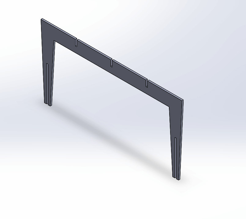
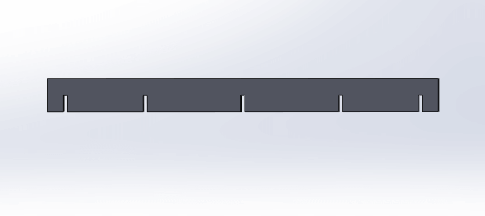
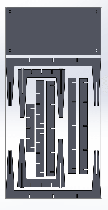
The design I settled on was simple. Long joints in the legs that would connect the exterior frame and then supporting beams in the middle. On the short lengths of the exterior frame I also inserted notches that would tie into the top and hold everything together.
Modeling
Ok, solidworks. I can honestly say I have never worked with a more frustrating CAD program. Solidworks is archaic, unwieldy and byzantine. Doing the simplest things is difficult and requires a lot of clicks. All of that said, it is really powerful. I did the modeling on the short length shown above with sketches and constraints. I ran into an issue with not being able to write equations that required about three re-installs (frustrating). Once I got the system running properly and got used to using construction lines to constrain the model, the rest of the drawing went pretty easily.
Now, where Solidworks really shines is being able to take parts and put them together into an assembly, which is essentially a 3D model that consists of smaller 3D models. I used this functionality to do two things. First, I used it to test if all of my joints were lining up correctly. This was a huge help when I went to adjust the material depth in the final models before cutting. I could look at the 3D model and see where the edits had made errors.
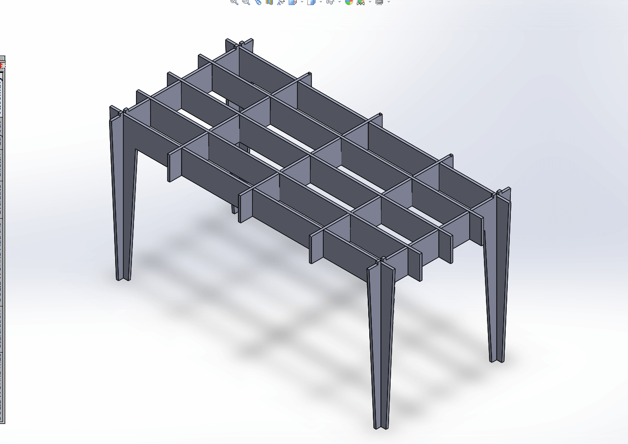
Second, I made a second assembly to layout the cuts on the material.
CAM
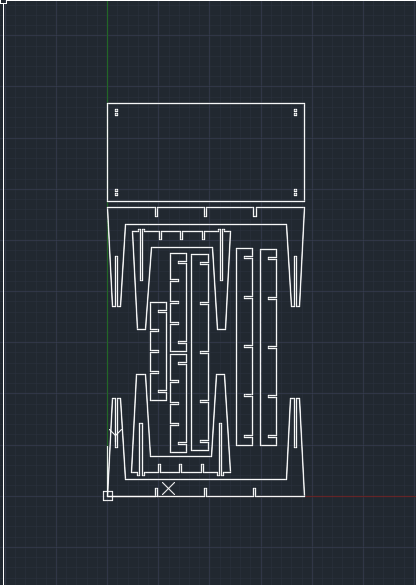
My final challenge with Solidworks was getting it into a dxf type file to move to MasterCAM. This makes no sense because Solidworks can easily export dxf from parts type files, but it cannot do the same thing for assemblies. I settled on a workflow that went from Solidworks to AutoCAD. AutoCAD was unable to import .assm files from Solidworks, so I ended up having to export parasolid. The model imported into AutoCAD as solids and I had to explode the geometry and then delete everything but the geometry in the z=0 plane.
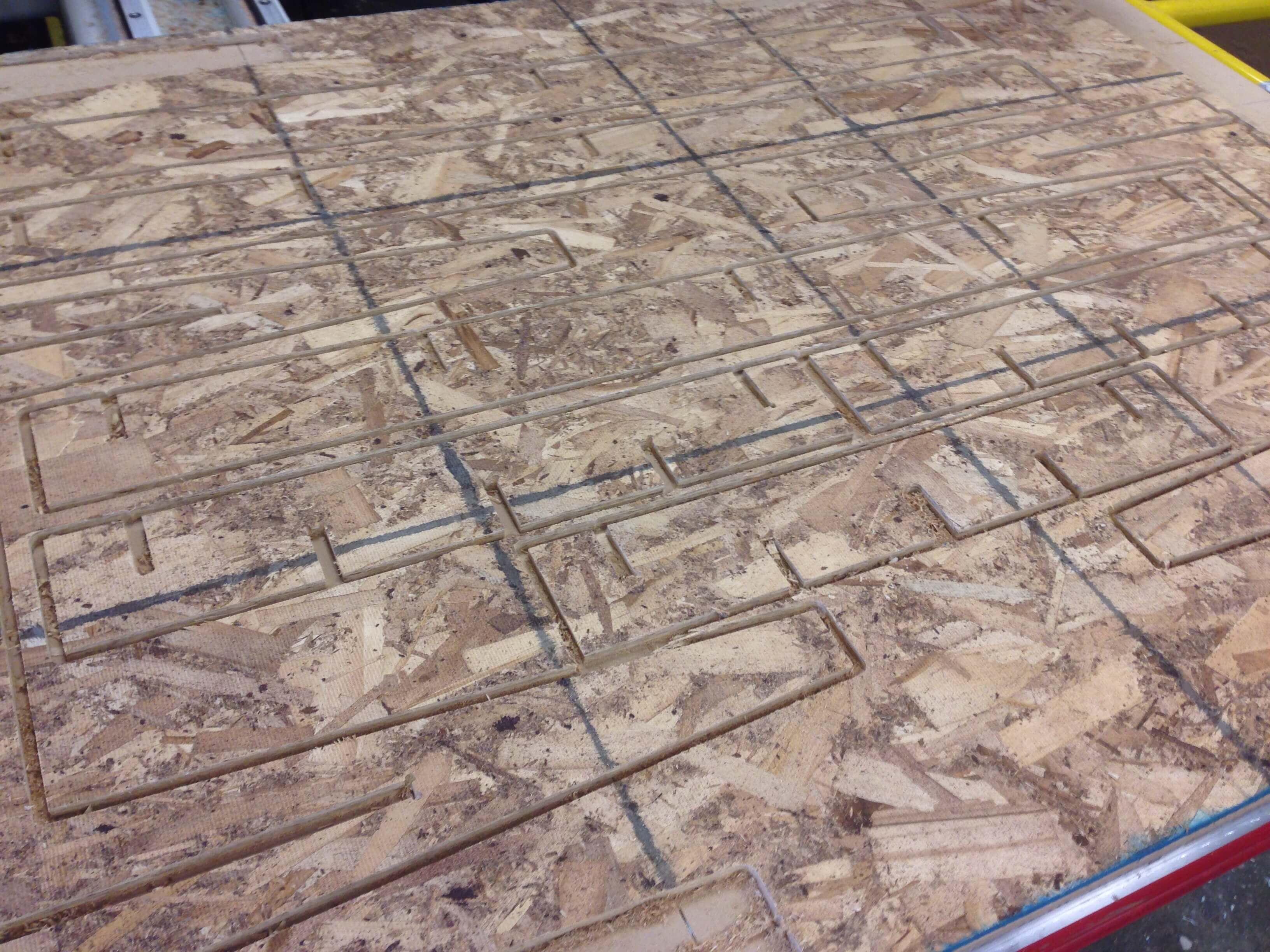
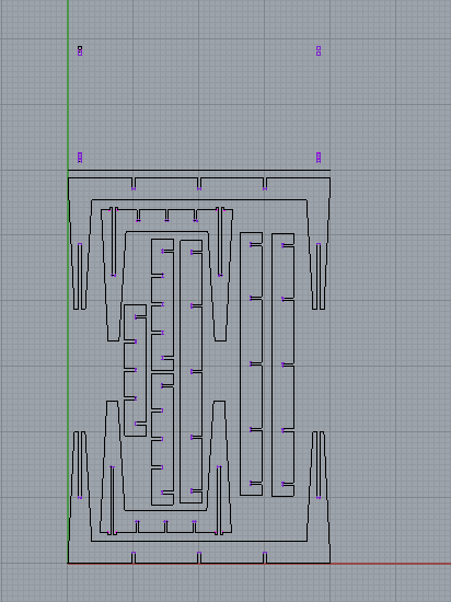
It was really important to t-bone the joints of the table properly because it would not fit together. In initial discussion with the TAs and shop managers we thought that just drilling holes at each of the joints corners would perform the operation without any additional CAD work. Unfortunately, the only bit that was loaded in the Onsrud was a quarter inch bit and we were milling with a 3/8 endmill. The result was that the path and the hole would not intersect (we saw this in MasterCam, which I think is an impressive feature). So it was now off to Rhino to add a new t-bone layer.
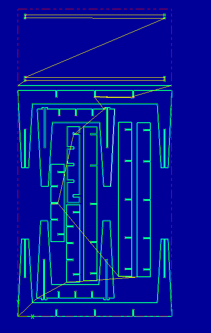
Finally, we were ready to import into MasterCAM. Despite its reputation for being complicated, MasterCAM at its core is a pretty simple program. You tell it what tool you want to use, which paths you want to cut out, and some adjustable parameters (feed rate, cut depth, etc) and it builds the toolpath. You link a series of toolpaths together (i.e. a contour cut, followed by hole drilling, followed by the final cut.) An important detail that everyone should know: MasterCAM only works in inches!
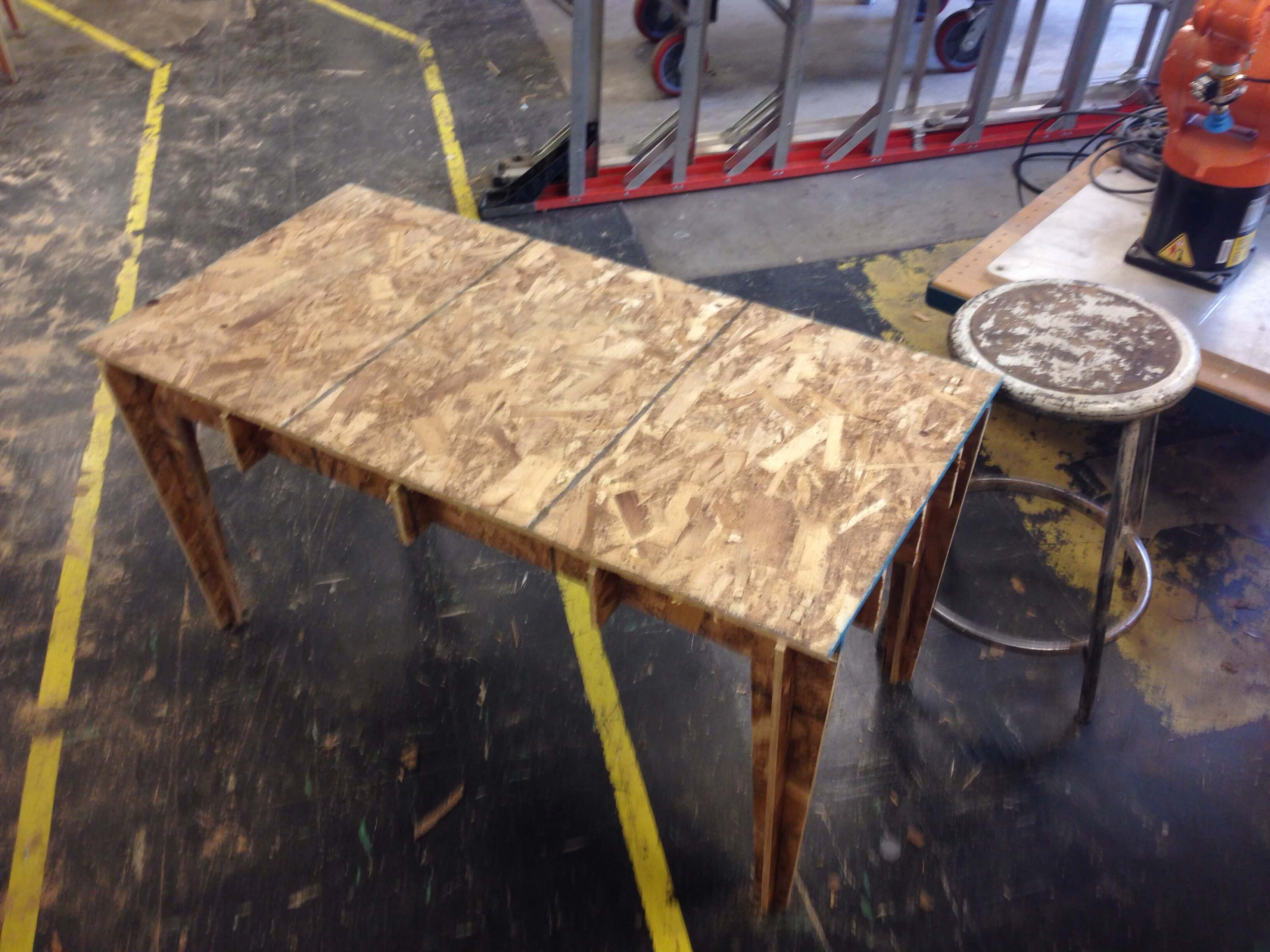
Cutting and Assembly
All of that work and all of that time. Now the payoff. Watching the Onsrud cut out the table was worth every second of messing around in the CAD workflow. It’s a thing of beauty. The table came together really easily and the final product was strong (I could stand on it).