Week 10
Input Devices
This week, I wanted to combine an input and an output devices because last week, I wasn't aware that I needed to design a new board based on Neil's designs. This week, I tackled combining two boards -- the servo and the phototransistor board. I encountered some interesting problems that I think taught me more about PCB design. Coding is what I need to tackle next!
****UPDATE: I fixed this and got everything working in Week 11!****
I designed a new board based on the servo board from Output Devices and the Phototransistor board from Input Devices. The goal was to create a board that would take light inputs from the phototransistor, map those values into the servo, and move the servo from one end to the other end based on the light intensity.
Before working with Dan Chen, I initially started by taking the phototransistor board and adding the servo components to that board. However, I quickly realized that the problem was much easier to solve than I had thought.
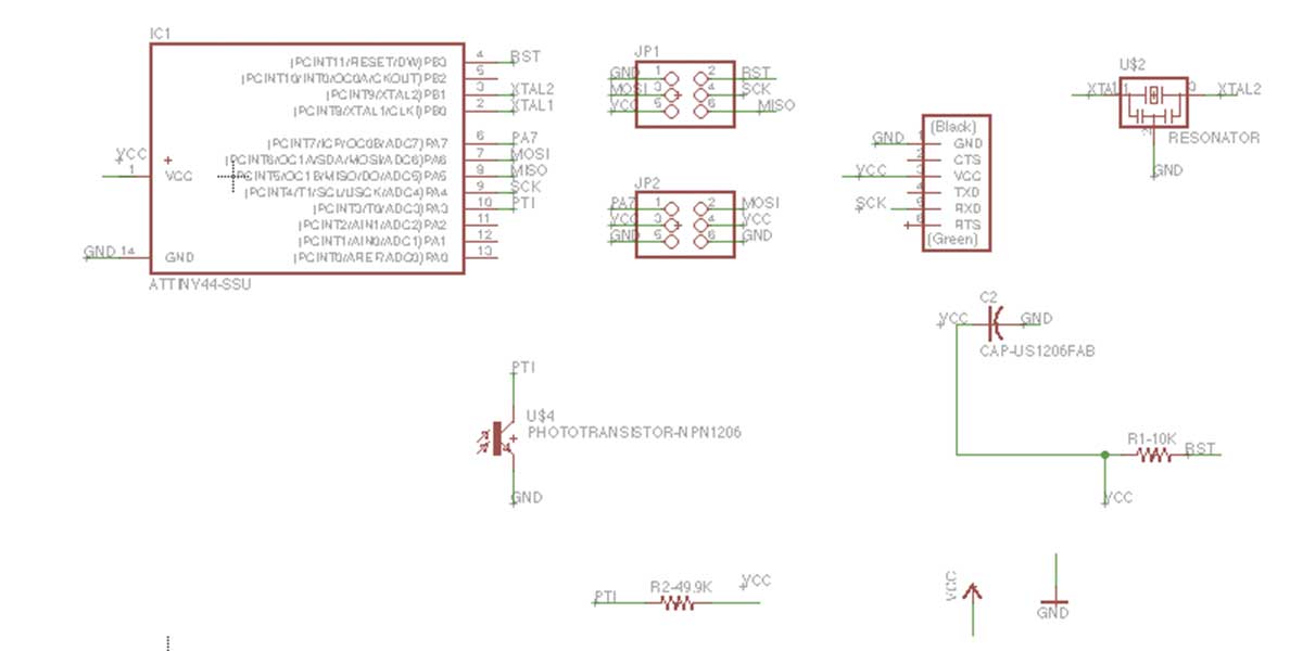
WIth Dan, we were able to deduce that we could actually take out the regulator, and simply add the 49.9k resistor + phototransistor to the corresponding pin from the ATTiny45 to the ATTIny 44a. I also replaced the power pins from the 2x3 to the 6pin FTDI to connect to the phototransistor.
Above is my schematic and below is my board traces/outlines.
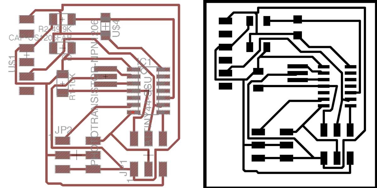
I ran into some problems with the Modela this week, including having traces that were too close to each other, but I was able to cut them apart with an Olfa and it worked out fine.
I also ended up breaking my first bit-- the 1/32" bit went through its first depth cut and it pulled and snapped the tip. I had to use the metal bandsaw to cut the board, and unfortunately, it did not come out too nicely. Still functional, but the FTDI pins are floating... ):
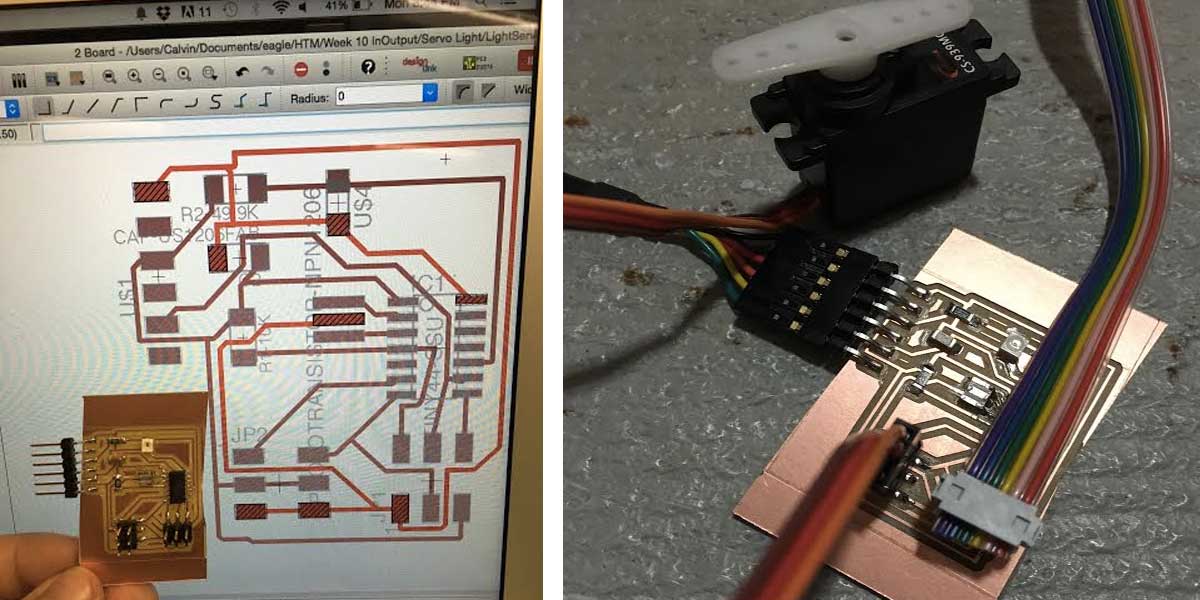
I then tried to program my board. This is where I ran into the majority of my problems. I was able to get the servo to sweep using the sample code from Arduino, but I was unable to get a read from the phototransistor.
I got several errors depending on what kind of code I used-- I was attempting to find some templates, as I don't have any coding experience and I wanted to get a sense of what went on. Dan and I tried to write some code, but it did not work-- the servo would initially move and shake a bit, and then it would stop moving, unable to really do anything.
#includeSoftwareSerial mySerial(2, 1); // RX, TX #include Servo myservo; // create servo object to control a servo int lightsensepin = A3; // analog pin used to connect the potentiometer int val; // variable to read the value from the analog pin void setup() { myservo.attach(A6); // attaches the servo on pin 9 to the servo object } void loop() { val = analogRead(lightsensepin); // reads the value of the potentiometer (value between 0 and 1023) mySerial.write(val); val = map(val, 0, 1023, 0, 180); // scale it to use it with the servo (value between 0 and 180) myservo.write(val); // sets the servo position according to the scaled value delay(15); // waits for the servo to get there }
It took the "KNOB" example code from Arduino, but instead of using a potentiometer to move the servo, it would take in the values from the phototransistor (values that range usually from 0 - 1024) and map them to servo values (0 to 180 degrees). Maybe I can go back to this this coming week and figure out what went wrong.
After that failing, I tried to just use Neil's code-- however, there seemed to be a problem with Arduino and the "Serial.begin" / PWM stuff. Again, I don't really understand all of this yet, but I'm hoping that it will be cleared up soon for my final project.