Week 13
Final Project
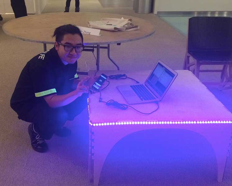
I created a table for the hall's lounge-- it has several different functions for whoever is in the lounge, and it will serve as a great addition to the community!! It includes a pressfit, 5-legged table, with a PCB of LEDs, a microphone, and a switch.

I started with a simple design for a table. I wanted to create something with similar dimensions as what we have at home-- about 3' x 3' and about 18" tall, which I think is better suited for our lounge and couches.
It's super lightweight, and is easily transportable. It used less than a sheet of plywood, and can be stood on by more than 2 people. (Shoutouts to Nadya for helping with transportation!)
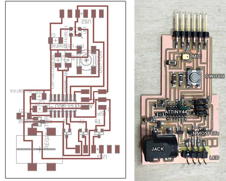
I designed a new board that connected a 12V LED strip, button, and the MEMS analog mic together. My idea was to use the mic and the button as the input and the LED as output. From this, I learned about the importance of mosfets, regulators, and how to connect larger power sources.
It took me quite a while to get this all to work, as I had a short somewhere and I ended up remilling several different boards of the same design to get something working. In the final board, there were two traces that had not milled completely, but I was able to quickly identify them with the multimeter and cut them apart. As you can see, I also used a jumper to fix a trace that I had ripped off the board.
We did a quick test -- the above was done on the vacuum/multitherm. We started with 210 C, heated very briefly, and then put it into the top with a makeshift mold. This came out really quickly, but was more brittle and did not flow well.
Finally the code:
I was really unfamiliar with how to approach this at first. It seemed incredibly strange, and I don't think I still had a great understanding of Neil's code (but more of a me-not-understanding-C problem). I explored more of Arduino, and discovered many things.
It's actually very easy to do what I wanted to do-- Arduino makes ADC really easy and Serial very easy as well. Setting up was the most difficult, and I think that was something I was really worried about, before I realized that Arduino is actually capable of simplifying a lot of what C does, i.e. Arduino is C with black box shortcuts.
I commented the code, so that should help anyone who is confused!
// Sensors
#include
SoftwareSerial Serial(2, 4); // RX, TX
int sensorPin = A2;    // select the input pin for the potentiometer
int sensorValue = 0;  // variable to store the value coming from the sensor

// LEDs
int RPin = A7;      // select the pin for the LEDs
int GPin = A6;
int BPin = 8;

// Buttons
int buttonPin = A3;
int buttonPushCounter = 0;   // counter for the number of button presses
int buttonState = 0;         // current state of the button
int lastButtonState = 0;
int bao;


void setup() {
  // declare the ledPin as an OUTPUT:
  Serial.begin(9600);
  pinMode(sensorPin, INPUT);
  pinMode(buttonPin, INPUT_PULLUP);     // INPUT_PULLUP
  pinMode(RPin, OUTPUT);
  pinMode(GPin, OUTPUT);
  pinMode(BPin, OUTPUT);
}

void loop() {
  // read the value from the sensor:
  sensorValue = analogRead(sensorPin);
  Serial.println(sensorValue);
  delay(100);

//read the pushbutton input pin:
  buttonState = digitalRead(buttonPin);

//
  if (buttonState != lastButtonState) {
    // if the state has changed, increment the counter
    if (buttonState == LOW) {
      buttonPushCounter++;
      Serial.println("on");
      Serial.print("number of button pushes:  ");
      Serial.println(buttonPushCounter);
    } else {
      // if the current state is LOW
      Serial.println("off");
    }
  }
  lastButtonState = buttonState;

//Off:
  if (buttonPushCounter == 0) {
    digitalWrite(RPin, LOW);
    digitalWrite(GPin, LOW);
    digitalWrite(BPin, LOW);
  }

//Mode 1 BLACKLIGHT:
  if (buttonPushCounter == 1) {
     bao = sensorValue-130;
     analogWrite(RPin, bao);
     digitalWrite(GPin, LOW);//sensorValue *255/300);
     analogWrite(BPin, 255-sensorValue);//sensorValue *255/300);
     //}
  }

//Mode 2 STROBING IF TOO LOUD:
  if (buttonPushCounter == 2) {
    if (sensorValue >100) {
      digitalWrite(RPin, HIGH);   // turn the LEDs on (HIGH is the voltage level)
      digitalWrite(BPin, HIGH);
      digitalWrite(GPin, HIGH);
      delay(30);               // wait for however long
      digitalWrite(GPin, LOW);    // turn the LEDs off
      digitalWrite(RPin, LOW);
      digitalWrite(BPin, LOW);
      delay(30);
  }
  }

      //Back to 0:
      if (buttonPushCounter > 3) {
        buttonPushCounter = 0;
      }

//Mode 3: FADE
  if (buttonPushCounter == 3) {
      if(buttonState == HIGH){
      int redVal = 255;
      int blueVal = 0;
      int greenVal = 0;
      for( int i = 0 ; i < 255 ; i += 1 ){
           greenVal += 1;
           redVal -= 1;
           analogWrite( GPin, 255 - greenVal );
           analogWrite( RPin, 255 - redVal );
            delay( 20 );
      }

          redVal = 0;
          blueVal = 0;
          greenVal = 255;
      for( int i = 0 ; i < 255 ; i += 1 ){
           blueVal += 1;
           greenVal -= 1;
            analogWrite( BPin, 255 - blueVal );
            analogWrite( GPin, 255 - greenVal );

             delay( 20);
      }

          redVal = 0;
          blueVal = 255;
          greenVal = 0;
     for( int i = 0 ; i < 255 ; i += 1 ){
          redVal += 1;
          blueVal -= 1;
            analogWrite( RPin, 255 - redVal );
            analogWrite( BPin, 255 - blueVal );

             delay( 20 );
  }
}
  }
  }
The final project was very successful! It worked wonderfully and I was able to get three settings: one for social times, in which the lights would pulse to music; one for anti-social times, in which the lights would pulse angrily if it was too loud; and a final continuous fade for calmer times.