Week 6
Electronics Design
This week, we had to design the PCB schematic and board from scratch. I thought it was going to be incredibly difficult, but it wasn't too bad! Using Eagle, I was able to design the schematic (with much help from Dan Chen's website), milled the board, and stuffed it.
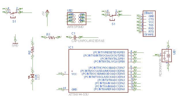
This was the first time that I have used Eagle to design PCBs. I added in the fab.lbr library into Eagle and began designing the schematic. I had to redo my schematic 3 times because it got extremely messy and difficult to follow-- I ended up using the NAME function to make connections, but I had a problem with not being able to see the names/connections... I also had some confusion with connecting the switch/LED/resistor, because I had no idea where to connect them. I ended up looking at past years' schematics and figured it out from there.
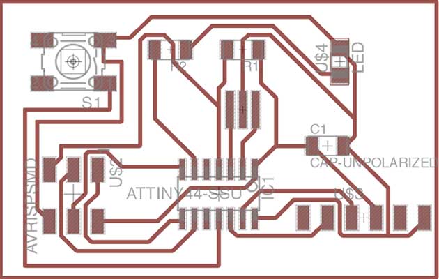
I played around with the auto route with the board design, and it actually worked pretty well! It was an interesting optimization process, but a lot of the trials never fully completed. I ended up using one of the designs as a base and drew new lines to finish up.
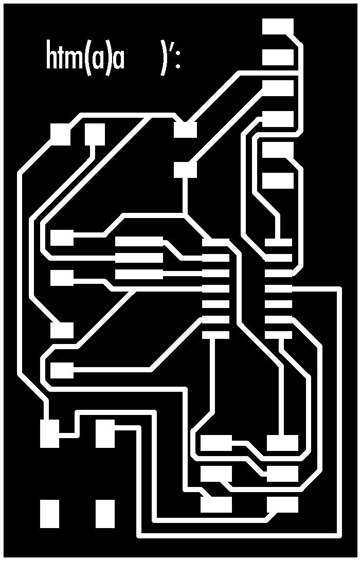
This is the trace and outline that I milled out on the Modela-- everything came out really nicely and only took ~15 mins.
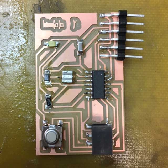
I've gotten much better at soldering! The things that tripped me up were:
- - direction of LED
- - direction of switch (I figured out that if I connected diagonally in the schematic, it wouldn't have mattered)
- - soldering the resonator is really, really difficult…