HTMAA - Week 3: Computer-Controlled Cutting
Week 3 is about milling PCBs (Printed Circuit Boards). They have the name despite the fact that they are rarely actually 'printed'. In our case, we were milling the boards from a substrate that is initially covered in copper. We use a Roland MX-20.
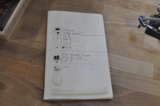
First step: Collect all the parts. The main difference here is that the parts are surface mount. When handling these with tweezers, if you aren't careful, they'll snap out of your grasp and disappear forever instantly.
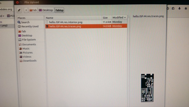
Next, you will find the two images for milling. One is for the traces you will leave behind, one is for cutting out the outter shape of the board. (White is for high, black is for the parts that will be milled off of the board.)
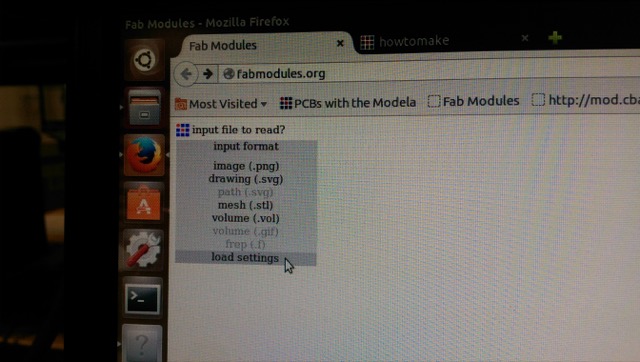
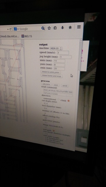
When initially bringing up Fabmodules, you will need to load the settings from the file on the desktop configured for use with the MDX-20.
When the settings are set, you first load the traces to mill.
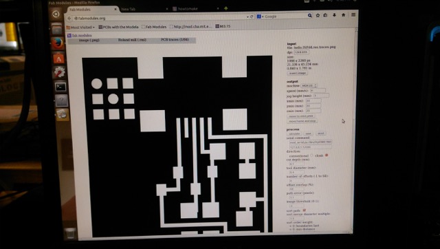
Speed can be an issue depending on the age of the end-mill. Since we are unsure of the age of this particular end-mill, the speed will be set down to 3 from the default 4. Once the settings are good, calculating will show you the tool path. The number of passes determines how cleaned up the unused board space will be.
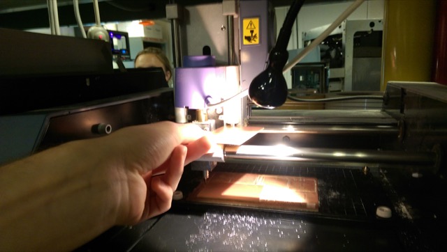
The x and y zero points need to be configured to the bottom left of your board. The z-axis needs to be as close to the board as is reasonable. Too high and the extra torque on the end-mill while moving laterally will strain and possibly damage it. The space on the MDX-20 as shown here for the z-axis should not be much more than the thickness of a PCB.
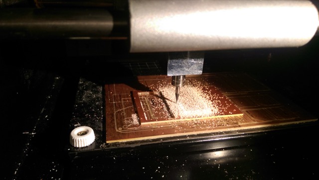
Once all of these settings are correct, run the job and the milling will take place. You can pause during the process to double-check things.
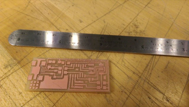
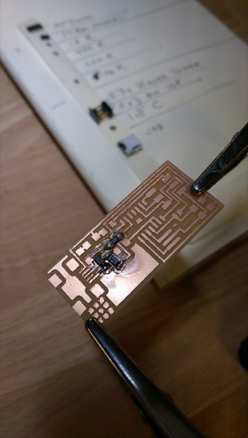
Now you have a milled board. If the base/sacrificial layer underneath is not perfectly flat, you will see what I see here: half the board has very clean traces milled, and the other half gets pretty messy and burred. Fortunately it wasn't so bad that it was unusable.
Next step is to stuff the board. Putting down a small flow of solder and heating up the trace, solder, and part that you want to flow the solder to is key. Whatever is heated is where the solder will flow.
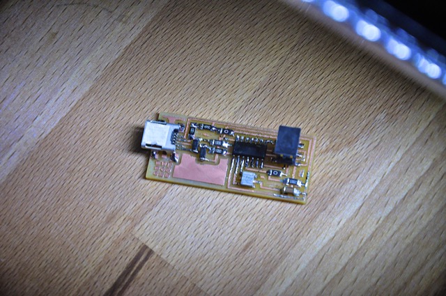
Here is the complete board. Not bad after some initial messy solder joints. Make sure to clean up your joints by teasing them out after the fact and making them shiny.
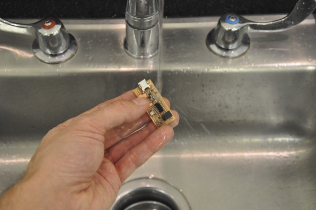
Wash the board afterward. All of the parts are made to be safe to wash. This removes the oils that will cause corrosion after months of use.
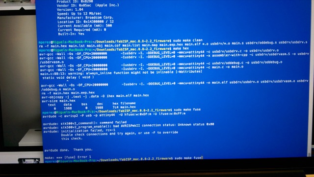
Next, attempt to program the board. You need a programmer to program this programmer, as shown here.

The first attempt to program my board failed. I built the design with the resonator, which has three contacts. I heard a rumor that some of these parts are out of spec, so I removed that part and tried a replacement.
After replacing the resonator, the programming succeeded! Since this only needs to happen once, we can now remove the 0 resistors and the board is ready to be used as a programmer.

Setting up programming environment:
- AVRDude ./configure listed missing libraries
- make failed horribly
- 'Crosspack for AVR' to set up tools and environment in OS/X 10.10.5
- other option is sudo apt-get avrdude
- https://www.obdev.at/products/crosspack/download.html