HTMAA - Week 8: Embedded Programming
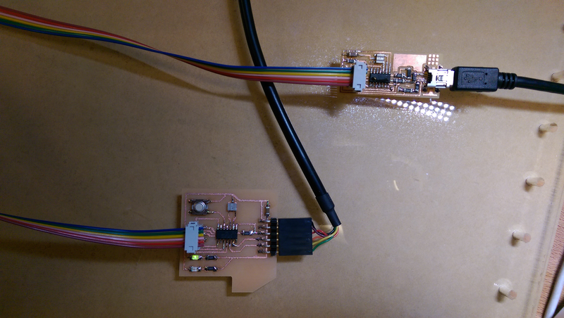
Week 8 is about programming embedded micro-controllers or integrated circuits (IC's). The main goal is to set up the workflow that allows for writing of custom code to the memory of an AVR chip in order to control the chip's functioning and some peripherals connected to it. I programmed my board from the previous Electronics Design class to hold a green LED solid when no interaction was happening and when the button was pressed, to flash a red LED.

Also, for the Networking and Communications recitation, I flashed the ESP8266 breakout board to its original AT command firmware and tested manually issuing AT commands via the FTDI cable, connecting it to the MIT GUEST network, and having it respond to HTTP requests with simple text output.

Links:
Embedded Programming Notes by JBobrow for getting C programs onto an ATtiny using the FabISP:
- https://gist.github.com/jbobrow/515b3c1dc0ede2d49030
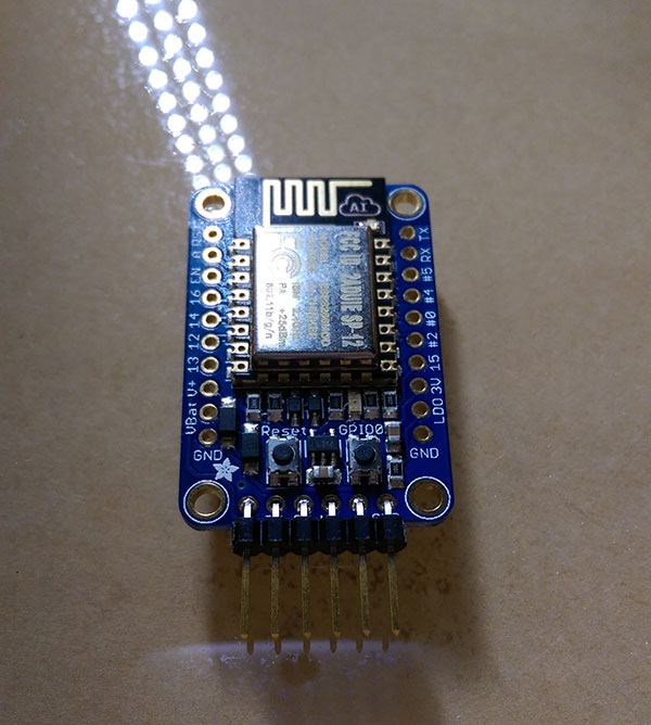
Wiring the breakout board:
- Bent surface-mount FTDI header to solder header pins flat with ESP breakout board
- Plug USB > FTDI onto header pins
- When plugging cable in, red and blue lights will flash but will not stay lit
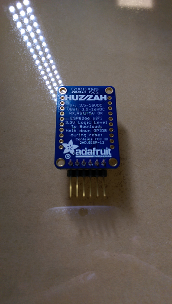
Setting up the ESP8266 (HUZZAH Breakout Board)
Flashing the AT command set firware:
- Setting module to bootloader mode
- Hold down reset button
- Press GPIO0 button
- Release reset button
- Release GPIO0 button
- Verify dull red solid LED indicator
- Port (From Arduino IDE via FTDI > USB): /dev/cu.usbserial-A603V09E
- Download https://github.com/themadinventor/esptool
- sands$ sudo esptool.py -p /dev/cu.usbserial-A603V09E write_flash 0x000000 v0.9.2.2_at_firmware.bin
 	Connecting...
 	Erasing flash...
 	Wrote 520192 bytes at 0x00000000 in 52.0 seconds (80.0 kbit/s)...

 	Leaving...
Testing the flashed module
sands$ ./esptool.py -p /dev/cu.usbserial-A603V09E read_mac
 	Connecting...
 	Traceback (most recent call last):
 	File "./esptool.py", line 532, in
 	esp.connect()
 	File "./esptool.py", line 159, in connect
 	raise Exception('Failed to connect')
 	Exception: Failed to connect
- Plug in USB > FTDI header
- Open Arduino IDE Serial Monitor
- Choose “Both NL & CR” for end of line
- Baud rate: 9600 (higher gives either no response, or strangely encoding characters in my testing; apparently newer models require this rate)
- Type “AT” and hit send/enter
- Verify that “OK” is returned
- If something is wrong (e.g. the end of line char, you will see “Error” returned
Other commands to try:
- AT+RST: Should reset the module and report “System Ready” when done.
- AT+CWMODE=3: Sets the module to both client and access point.
- AT+CWLAP: Will list SSIDs available
- AT+GMR: Report firmware version
- AT+CWJAP="ESP_F4E9C7”,””: Initially I thought I was supposed to try and send a command to attach to itself, which just returned “FAIL”
- AT+CWJAP="MIT GUEST”,””: This command is supposed to be for the module to connect to a wifi access point as a client. This returns “OK”.
- According to this document, “after next power down cycle module connects automatically to last AP”.
- AT+CWJAP?: Returns the currently connected to access point. I recevied +CWJAP:"MIT GUEST"
- AT+CIFSR: Get IP address
	192.168.4.1
	10.189.4.171

	OK
- When on the same WiFi Network:
- ping 192.168.4.1 just times out
- sands$ ping 10.189.4.171
 	PING 10.189.4.171 (10.189.4.171): 56 data bytes
 	Request timeout for icmp_seq 0
 	64 bytes from 10.189.4.171: icmp_seq=1 ttl=255 time=1.922 ms
	64 bytes from 10.189.4.171: icmp_seq=2 ttl=255 time=1.912 ms
 	64 bytes from 10.189.4.171: icmp_seq=3 ttl=255 time=23.487 ms
 	64 bytes from 10.189.4.171: icmp_seq=3 ttl=255 time=25.707 ms (DUP!)
 	64 bytes from 10.189.4.171: icmp_seq=3 ttl=255 time=36.819 ms (DUP!)
 	64 bytes from 10.189.4.171: icmp_seq=4 ttl=255 time=4.708 ms
 	64 bytes from 10.189.4.171: icmp_seq=5 ttl=255 time=4.336 ms
 	64 bytes from 10.189.4.171: icmp_seq=6 ttl=255 time=2.265 ms
 	64 bytes from 10.189.4.171: icmp_seq=7 ttl=255 time=29.542 ms
 	64 bytes from 10.189.4.171: icmp_seq=8 ttl=255 time=1.636 ms
 	64 bytes from 10.189.4.171: icmp_seq=9 ttl=255 time=5.392 ms
 	64 bytes from 10.189.4.171: icmp_seq=10 ttl=255 time=6.919 ms
 	64 bytes from 10.189.4.171: icmp_seq=10 ttl=255 time=7.039 ms (DUP!)
 	64 bytes from 10.189.4.171: icmp_seq=11 ttl=255 time=14.987 ms
 	64 bytes from 10.189.4.171: icmp_seq=12 ttl=255 time=2.598 ms
 	64 bytes from 10.189.4.171: icmp_seq=12 ttl=255 time=2.615 ms (DUP!)
 	64 bytes from 10.189.4.171: icmp_seq=12 ttl=255 time=46.488 ms (DUP!)
	64 bytes from 10.189.4.171: icmp_seq=12 ttl=255 time=46.592 ms (DUP!)
	64 bytes from 10.189.4.171: icmp_seq=12 ttl=255 time=46.872 ms (DUP!)
- AT+CIPSTATUS
	STATUS:2
	OK
Testing Web Responses
- Download https://github.com/guyz/pyesp8266
- sands$ python esp8266server.py /dev/cu.usbserial-A603V09E 9600 "MIT GUEST" "" (note blank password)
- Final setup / connect takes a while to respond, but succeeds eventually
- Response from the web should now succeed!
- Visit http://10.189.4.171/ in a web browser. Response should be:
GOT IT! (2015-10-31 19:58:20.038027)
Writing in C for ATtiny44


