Input Devices
Hall effect sensor
Hall effect sensor
This assignment was meant to attach an input device to your PCB and program it to work with the custom designed board.
I had a really busy month due to thesis crit. But, I still completed the assignment by attaching a hall effect sensor to attiny44 board that I developed and programming it using the arduino IDE.
My programmer went bad. So, I had to make the programmer again. But, this time I really focused on doing it well. I made the board like 3 times and soldered it properly. It worked in one go.
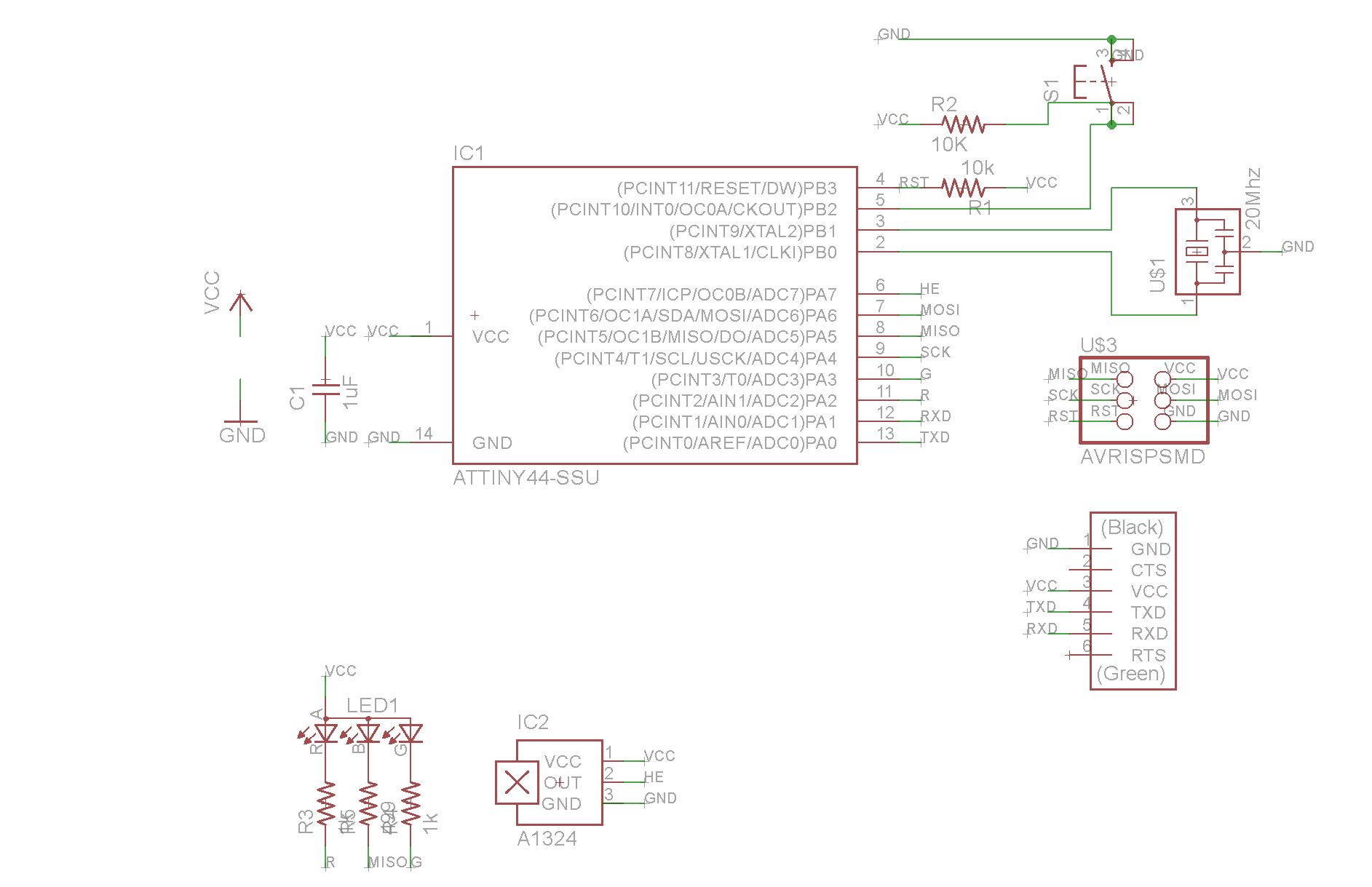
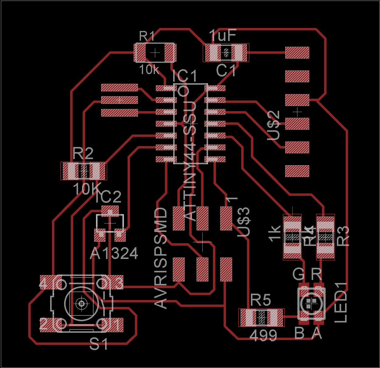
Then I modified by pre-designed Attiny44 board in Eagle and added a hall effect sensor to it. I milled the board in Modela, but it wasn't working very well. Seemed like we were out of 1/64" mills. Dan changed the mills and it worked okay.
Again, I soldered the board. But there were some joint connections. I realized that I had placed the wires too close in Eagle. But, I wasn't finding a good way to modify those without making drastic changes since there was so space.
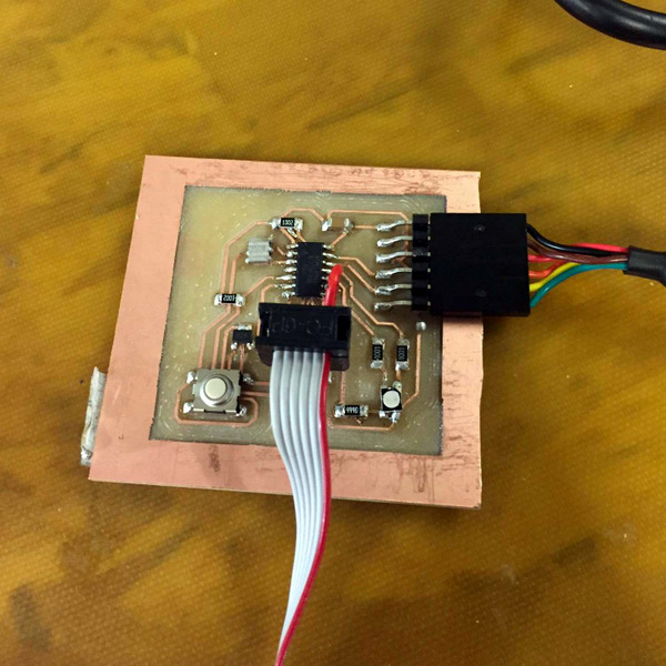
So, I resorted to using the exacto knife to cut tracks. While I was doing that, one of the connections broke. So, I planned on using jumper wire.
I had trouble with the jumper wire since there wasn't enough space. I spent half a day soldering the board, but it was worth it. As with the fabISP board, the board worked in the first attempt. But, I couldn't make the hall effect work with the serial communication interface from the C file. So, I used arduino IDE and High-low tech website to program attiny using the arduino IDE, and it worked well. I lit my RGB led with different color combinations whenever the magnetic field crossed a particular threashold. Bingo!