
Final Project
The goal of the final project was to incorporate many of the skills learned over the semester into one project. At the beginning of the year I had suggested an idea or two for a final project (Final Project Proposal), but over the course of the semester the idea changed just a bit. I decided that I wanted to make an internet connected terrarium for a few plants that could mimic the weather outside or anywhere in the world. As the idea became more solid, I started focusing my weekly assignments on developing parts that would be incorporated in my final project (Output Devices, Input Devices, Application Programming)
Tools+Skills
- 3D Modeling
- Autodesk Fusion 360
- Laser Cutting
- Laser Cutting
- Adobe Illustrator
- Kerf Bending Hinges
- 3D Printing
- Form1+
- RepRap Prusa
- Electronics Design and Production
- Eagle PCB Design
- Modela Desktop Mill
- PCB Assembly
- Molding and Casting
- Partworks3D
- Shopbot Desktop
- Blue Foam Molds
- DryStone (Plaster) Casting
- Embedded Programming
- C (Programming Language)
- Arduino IDE
- Output Devices
- Output Daughter Boards
- Water Pump
- LEDs
- Mist Maker
- Application Programming
- Processing IDE
- JSON Parsing
- Google Maps API
- Forecast.io API
Weather Mimicking Terrarium
The project proposal started off as an ambient device that could mimic the weather outside and allow the user to glance at it to see the weather (useful if you research lab doesn't have windows). I also played around with the idea that the device could fetch the forecast for the day or week, and play it through in condensed time so that you could experience and visualize the weather ahead of time.
Throughout the semester, I decided that it would be cool if the device had another purpose as well. I saw the popularity of plant terrariums start catch on for decoration and found myself wanting to buy one. The two ideas met and I decided it would be really cool if I could make a terrarium that could mimic the weather outside or anywhere in the world, so that you could experience the weather from the comfort of your windowless office, get a glimpse of nice weather in Hawaii when you are stuck in snowy Boston, or let your indoor plants get a taste of what it is like out there in the wild.
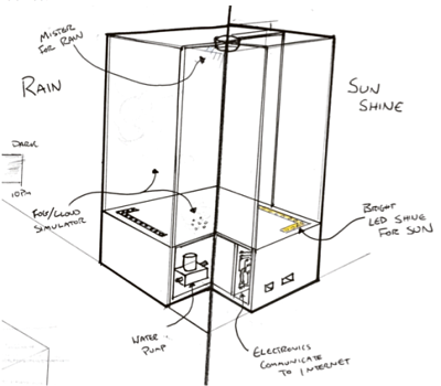
I started thinking of the design of what it may look like and sketched out my ideas as they came. Unfortunately, at the time of writing this I can't seem to find any of my many sketches, so I will have to explain. I imagined a container similar to what I had sketched out for my proposal, but this time with a planting bed for a few plants. The device would be roughly in thirds: a middle third would be the visible portion where the planter would be, the bottom third would have a water reservoir with a pump and mist maker, the top third would have LEDs and a drip tray to make a rain effect. For rain, the pump would pump water from the bottom reservoir up to the top drip tray allowing the water to drip down onto the planter and then drain back down into the bottom reservoir. For clouds, the mist maker would make a fog of mist that would raise out of the bottom third into the middle third through vents. For sun, the LEDs would shine down onto the planter.
Container
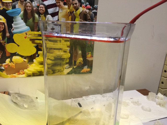
I knew that all of the functionality would be housed inside of a clear container. At first, I had decided to make this container out of clear acrylic that I could laser cut and then arcylic bond together. However, leaking water was a big concern of mine and design tolerance. I began designing the parts and actually started laser cutting out the parts, before I decided that it was a better use of my time to buy a container and modify it to my purposes. This way I could focus on the functionality instead of making a box. I went container shopping and landed on a clear plastic container that was tall and had a rounded rectangular cross section. This would allow me to drill holes easily and prevent making many circular parts, and provide a good viewing angle for the plants. This would also give me plenty of vertical room for all of my parts, with room to spare. Additionally, having a water tight container meant that I wouldn't need to design a separate water reservoir, the entire container could be one.
PCBs
With the container chosen, my next biggest hurdle would be to get all of the electronics working with the output devices. In the output device week, I had gotten the pump working with an old board, but my new intention was to use my Anduino board from input week with a daugther board for outputs.
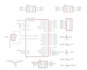
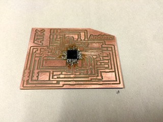
Brief recap on the Anduino, this was a modification of the FabDuino for my purposes. I designed the board to have a bunch of pins accessible for future daughter boards, not knowing how many I would need. (Eagle: Anduino.brd Anduino.sch)

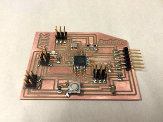
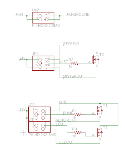
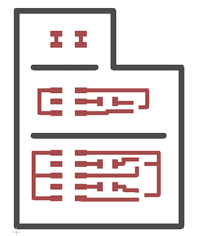
New this time around was my output daughter board, which I designed to have three segments, one for my 2 devices on 9V, one for my 1 device on 24V, and one for tying in board VCC and GND if needed.
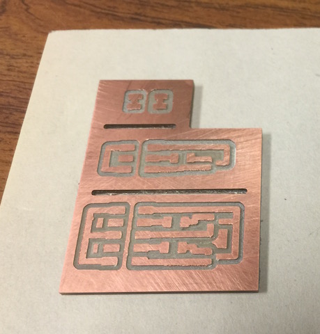
At first I was having a lot of problems, I was blowing MOSFETs and not having any control over my outputs. I realized I had everything messed up. I had the source and drain swapped and did not have pull down resistors. After new MOSFETs, added drop down resistors, and re-routing some traces I had a board that worked.
My new board was pretty hacked together, I planned on redesigning a new one or perhaps a holistic board if there was time, but alas there was not.
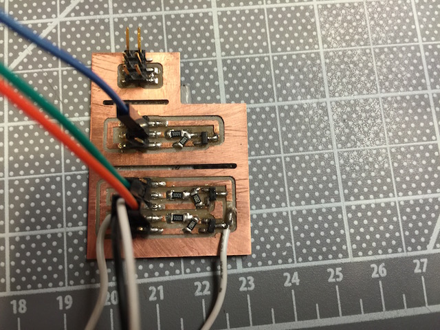
I then ran into a new problem, when all the devices were hooked up with their own power and ground they did not work because they did not share ground with the board. But no problem, just added some jumpers!
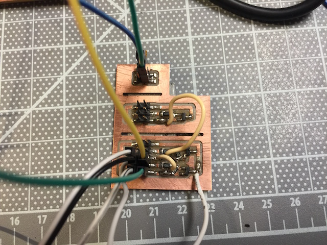
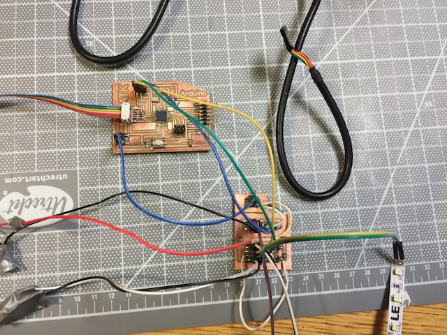
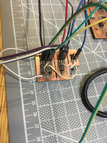
The way it works is: the bottom section of the board is for 9V for the LED and pump. The 9V power supply is rewired with female headers and drops power and ground (ground is tied to board and 24v ground too). The + and - for the LED and Pump each also have female headers. The + leads connect to 9V and the - to their own MOSFET drain. All MOSFET sources are on GND. Then from the board, each gate for the MOSFET is tied to a pin on the Anduino to trigger. The same sort of situation is on the 24V middle section. The top section brings ground from the board which is then distributed to all other grounds on the board (and MOSFET sources) with jumpers. Here it is all hooked up.
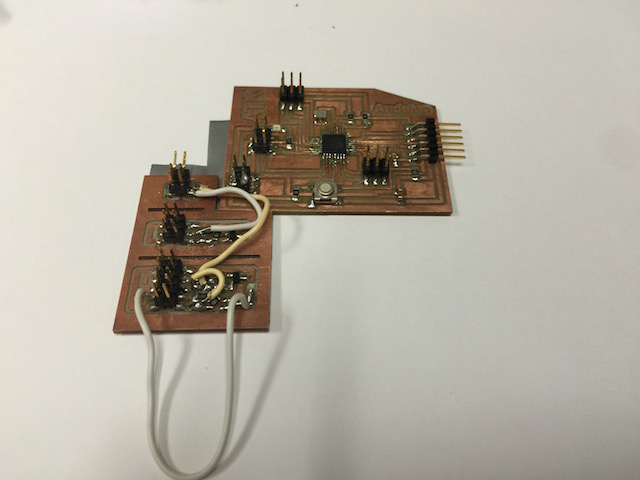
How about a shot of just the mother and daughter:
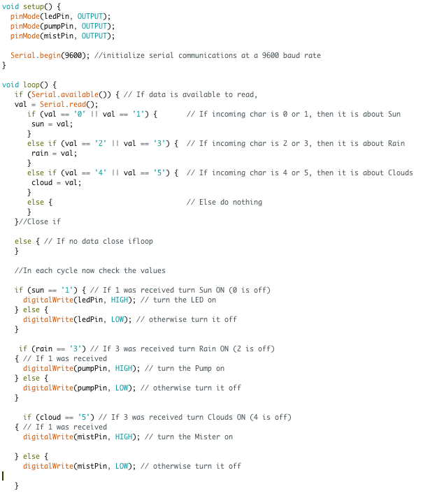
The microcontroller was programmed the same way as in the application programming week. It listens to the serial port (data sent from Processing). If the serial input is a 0 or 1 it controls off and on for the Sun/LED pin. If the serial input is 2 or 3 it controls of and on for the Rain/Pump Pin. If the serial input is 4 or 5, it controls off and on for the Clouds/MistMaker pin.
Testing Outputs
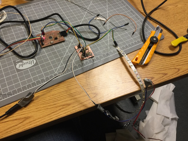
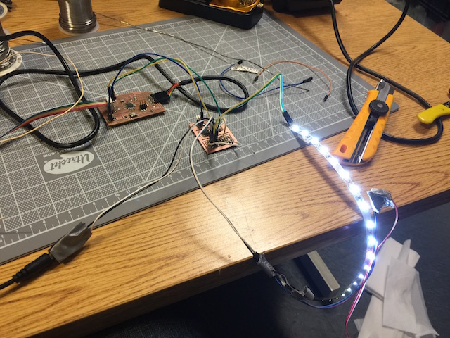
With the PCBs figured out, it was time to incrementally test the outputs. First up, I tested the LED strips with my controls.
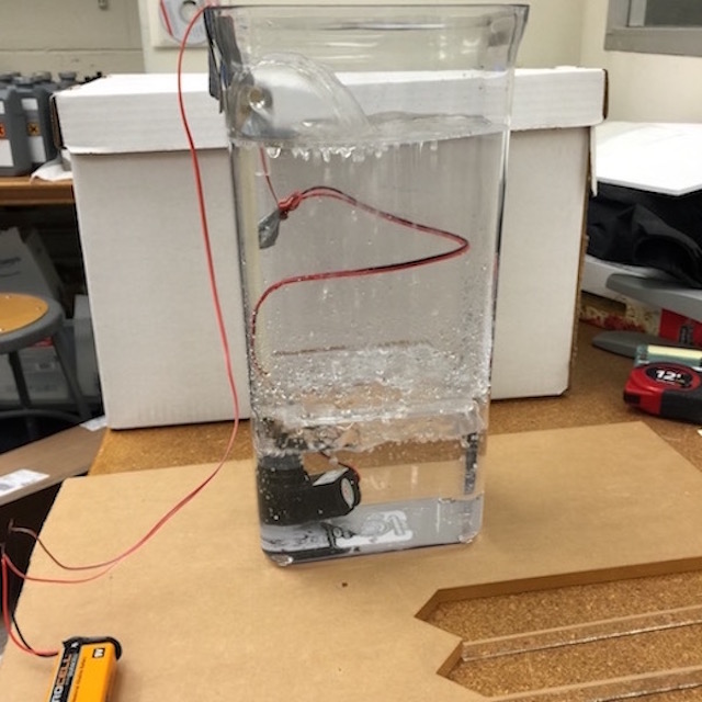
Next up was pumping:
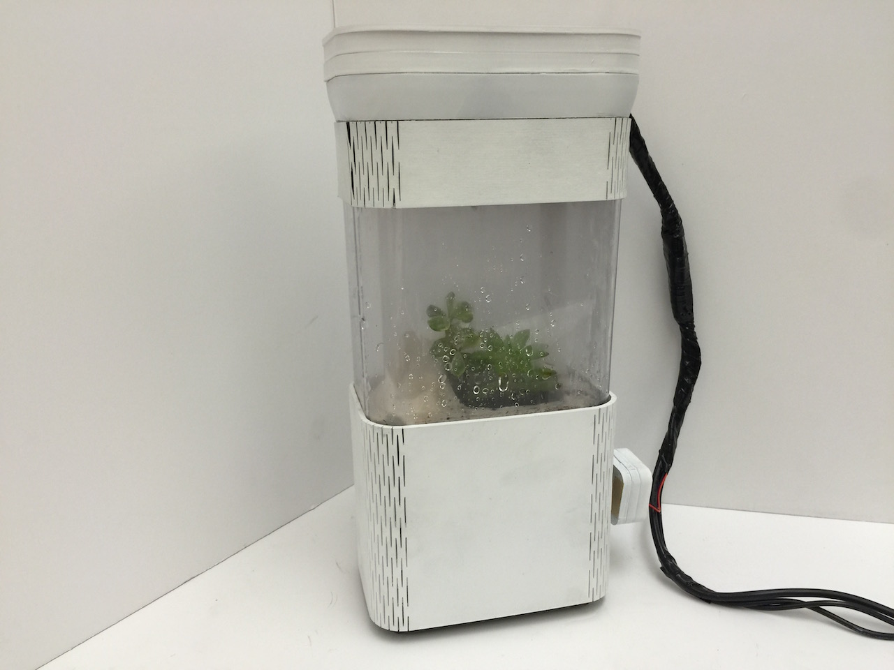
Next up was the mist/cloud maker:
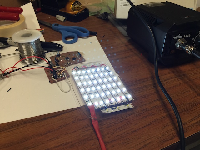
I then layed the LEDs out on an acrylic sheet that would fit in my container.

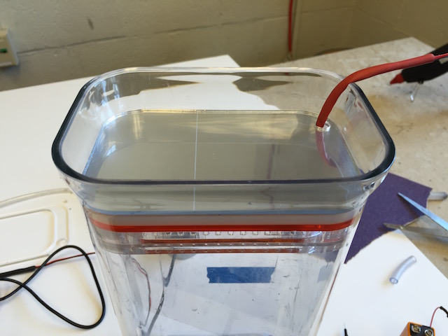
I also had cut out a drip tray for my rain effect and could now test the raining.
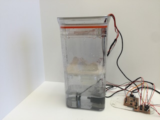
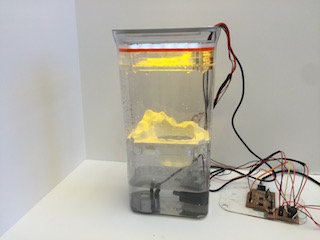
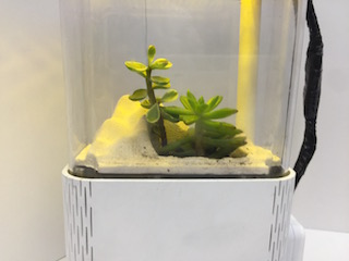
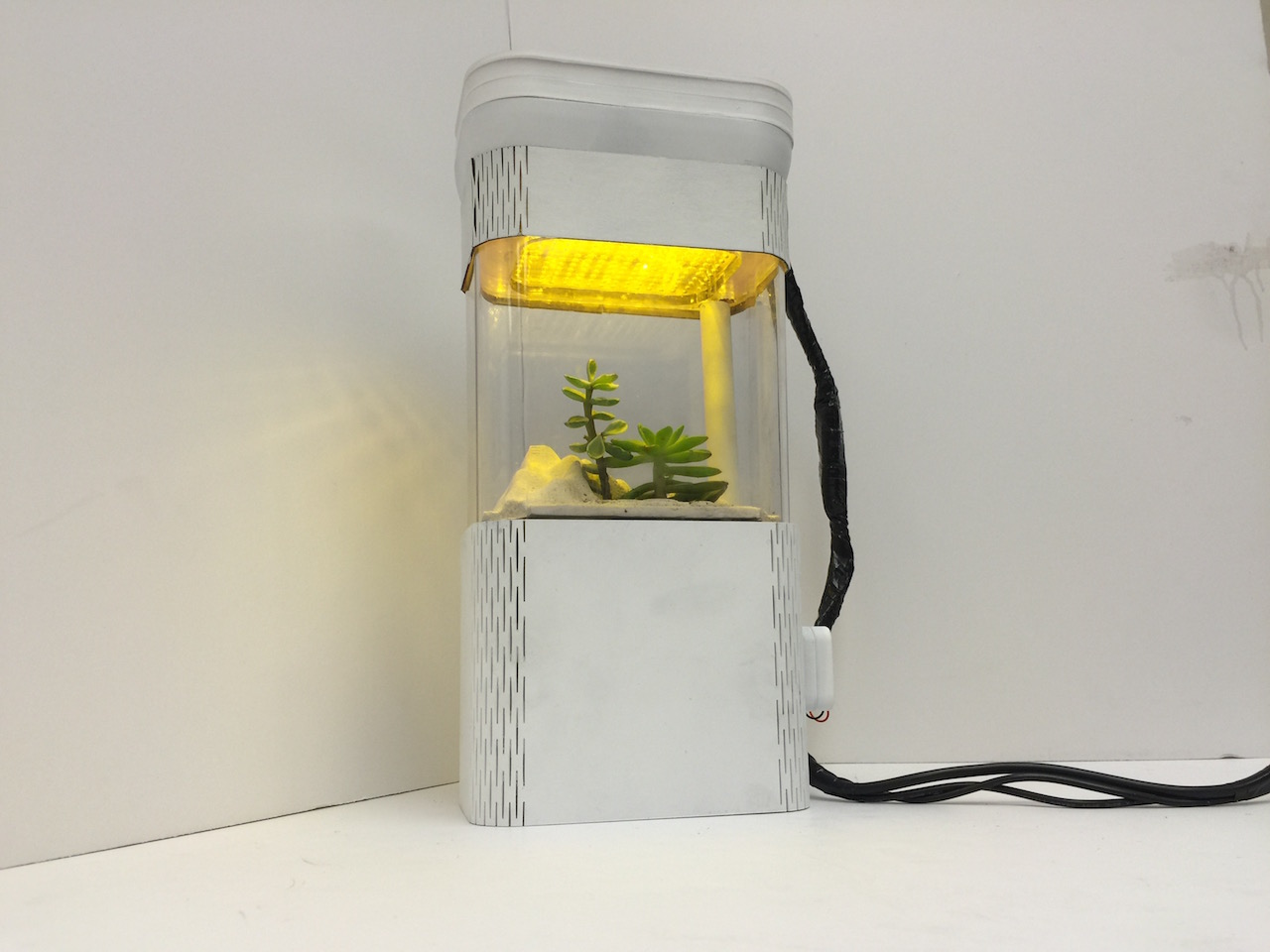
I could finally get a feel for what the effects would look like.
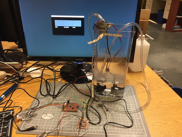
Finally, I could test all three together:
Planter
I now started my focus on the middle third, which I knew would have my planter with plants on display. I decided that plants alone were cool, but if I could add some added suggestions of terrain it would be even cooler! By nature, I am not a city person. I love hiking, fishing, and everything in the mountains. So I decided that I should design my planter to look like mountainous terrain. I could get small plants that look somewhat like small versions of big trees, sculpt in some mountains, and provide valleys where rivers could form with the falling rain. I knew also, that my planter would have to have drain holes where the water could drain down into the bottom reservoir and vent holes to let the clouds up.
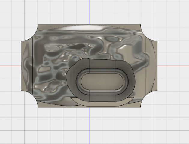
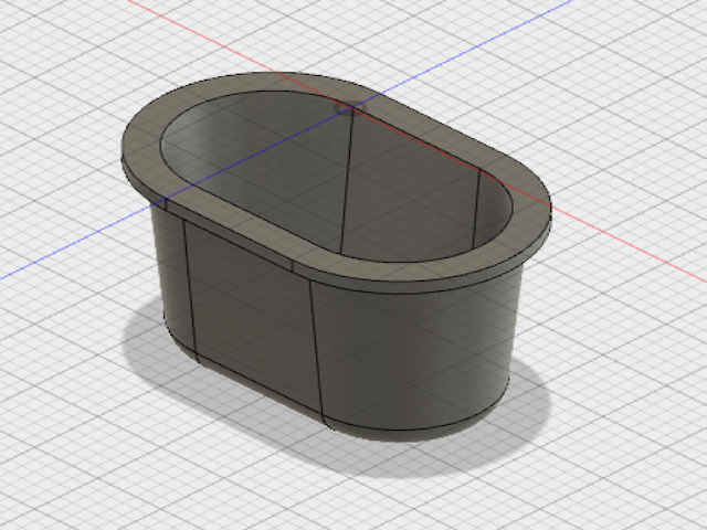
I knew that the terrain would be difficult to model in just any CAD program, but I was able to find out that Autodesk Fusion 360 had a sculpt model that could create freeform surfaces. I measured the inside of my container, which had a draft angle taper, and estimated a size that I thought would have an interference fit in the middle section of the container.
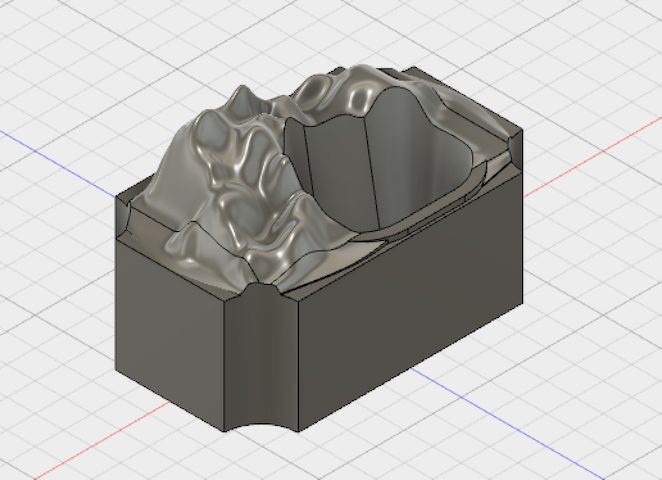
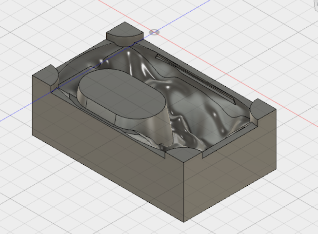
The design itself was a block with mountains on top, drain holes in the corners, and a deep holes for the plants to be planted in.
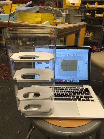
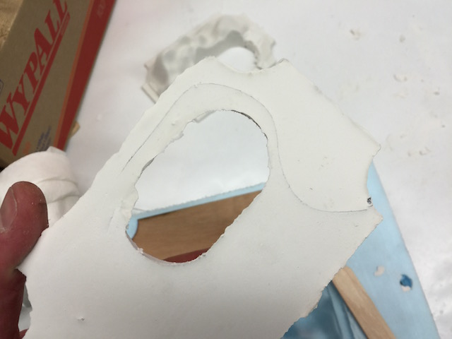
I then needed to tweak my design with the perfect dimensions to wedge in and stay in place right where I wanted it in the container, so I went to the laser cutter to quickly cut a bunch of sizes out of foamcore to test which size fit correctly.
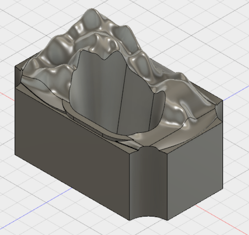
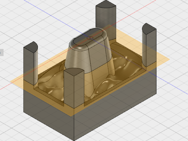
Once I figured out the correct size, I went back and tweaked my model. I then knew that since, I only needed one with one pull direction, I didnt have to make a silicon mold. So I subtracted my model from a block to get the negative that would be used for the mold.
I then rethought, the design, and realized that I didnt need the giant block of plaster, if I 3D printed the cup to hold the plants, so I cut the model in half to have just the mountains, drain holes, and a hole for the plants to poke through.
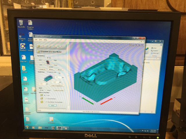
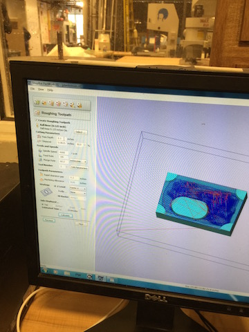
With the design ready to go, I hopped into PartWorks3D and generated my tool paths.
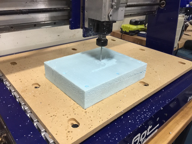
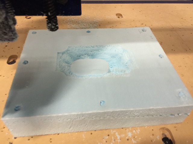
I then setup the shopbot desktop with a nice big block of blue foam and milled out my mold.
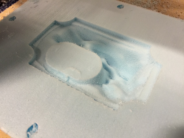
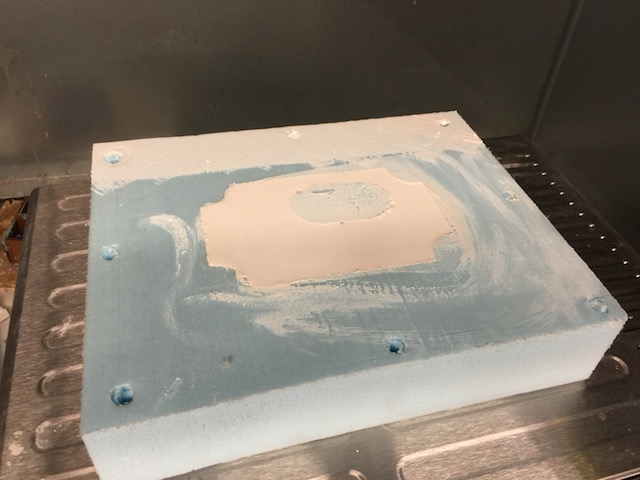
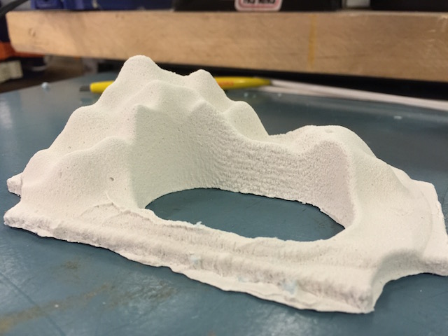
With the bluefoam mold finished, I mixed up a batch of DryStone plaster and poured my mold. The first time, the thin part of my mold came out too fragile and broke. So the second time, I did some make shift composite work and layed in long fibers through the thin part.
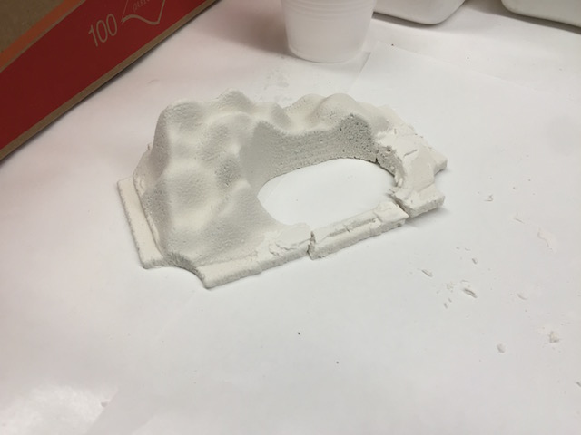
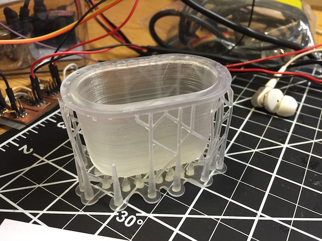
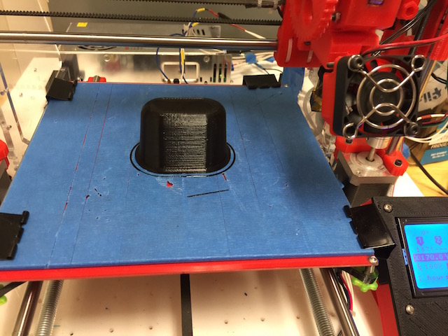
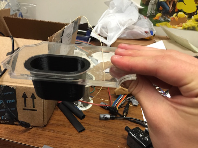
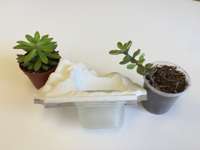
The part came out just like I wanted, so next I had to make the planter cup that would go below. I took the part from my 3D model and 3D printed it on the Form1+ and an FDM printer. Both parts came out really nicely, as you can see below, but I went with the form print as it matched my colors. You can see how the planter cup fits in on two acrylic plates.
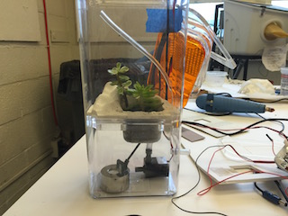
It came time to assemble the planter and see how it fit in the container. The planter had the casted mountain, the planter cup, and two acrylic cut sheets that held the lip of the planter and supported the mountains. Eventually I added a thicker bottom acrylic sheet so that placing them all in the container was less error prone. You can also see the plants I have chosen.
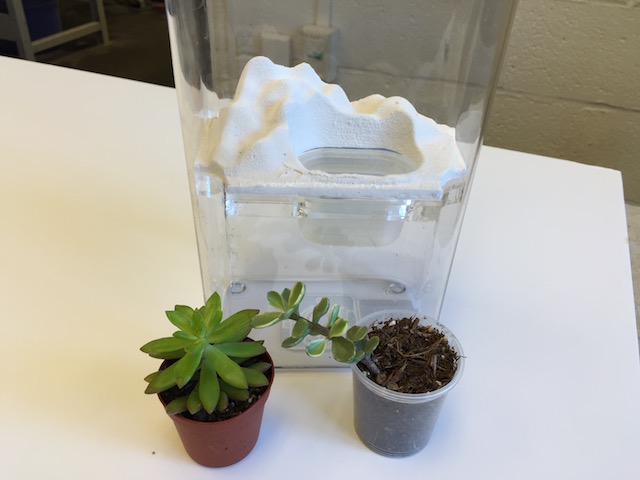
For now this module was done, but you'll see more photos of it in the assemby phases later.
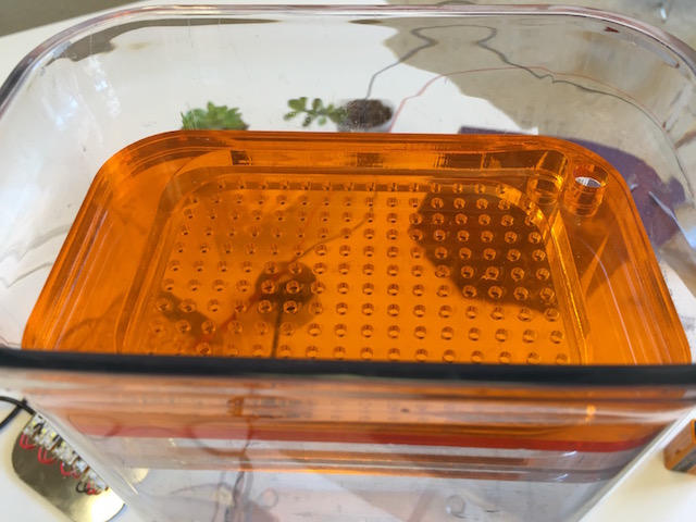
Top Third (Driptray and LEDs)
Since the bottom third was just for the pump and mist maker, the planter was done for the middle third, it was time for the top third. This section would house the drip tray for the rain effect and the LEDs for the sun effect. These components would also have to pass wires through them up to the electronics.
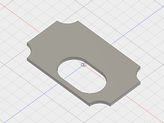
The images below show the different pieces making up the top third components:
This piece creates the interference fit with the walls of the container to hold everything above. The big hole in the center allows the rain to fall through. The small holes in the corner are pass throughs for tubing and wires.
This piece is the drip tray that has an array of small holes to let the rain drops fall through. The small holes in the corner are pass throughs for tubing and wires.
There are then two thick pieces ontop of the drip tray that form the walls for a little top reservior for any water that builds up. The center hole allows the tubing to enter this little reservior and then the water to drip through the drip tray below. It still has a wire pass through hole
This color plate serves two purposes. It forms the top barrier of the drip tray to keep the water out of things above (electronics) and also changes the color from the white LEDs to be a warmer sunny color.
This little white acrylic spacer just is an offset so that the downward facing LEDs above have room. Also the opaque material keeps the light from spreading sideways.

Next is the plate of LEDs, this is an array of LEDs on strips that is connected to the daughter board. This is cut on a piece of silver reflective acrylic in the hopes that it can reflect extra light down to the planter.
Finally, here are all of the sheets stacked together forming the top third guts. There is extra space on top for electronics in the future.

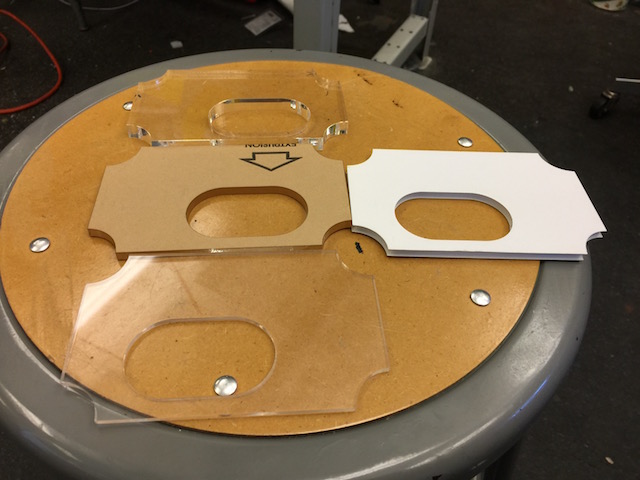
Below is the behind the scenes of me getting the sizes right:
Application Interface
The application interface was a crucial part of the concept. I wanted the user to be able to replicate the weather outside (or anywhere in the world) as well as control the weather themselves. In the future, I want the device to also be able to display the forecast for the day and week, I have the data for this, just not the functionality.
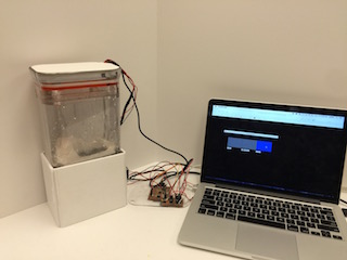
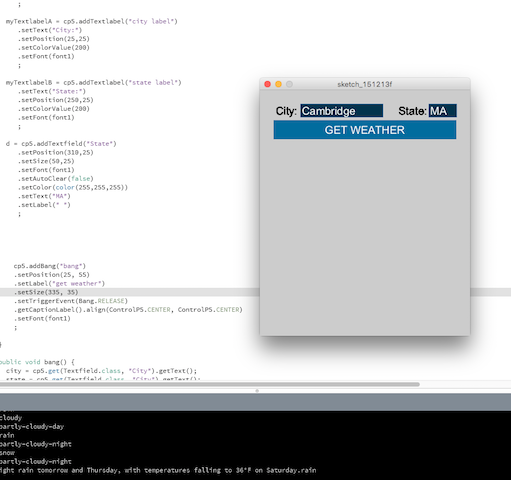
For all my testing up until now, I had been using a verison of the application interface I wrote for the Application Programming week. You may have seen it in the videos above. This worked just fine, so my focus was on incorporating the weather from a weather site.
I knew to get the weather data, I would have to do an API call to an online data site. At first, I got this up and running Yahoo Weather, but later switched over to Forecast.io for their hourly forecasts.
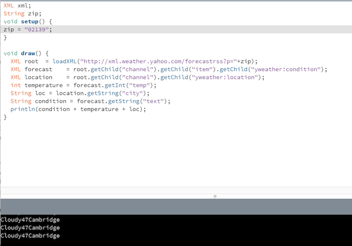
Although it took me a while to figure out at first, APIs ended up being somewhat straight forward. For forecast.io, you send an API request for a JSON file to their API call address and processing saves the resulting JSON file. You then must parse this to get what you are interested. In my case, I was interested in the one word weather descriptions ("cloudy", "sunny", "rain"). Below you can see me interacting with Yahoo Weather API to get the weather and temperature for Cambridge.
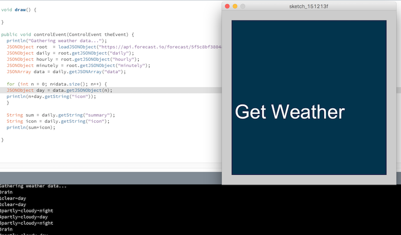
I then switched over to Forecast.io and was able to grab a weekly forecast for a location.
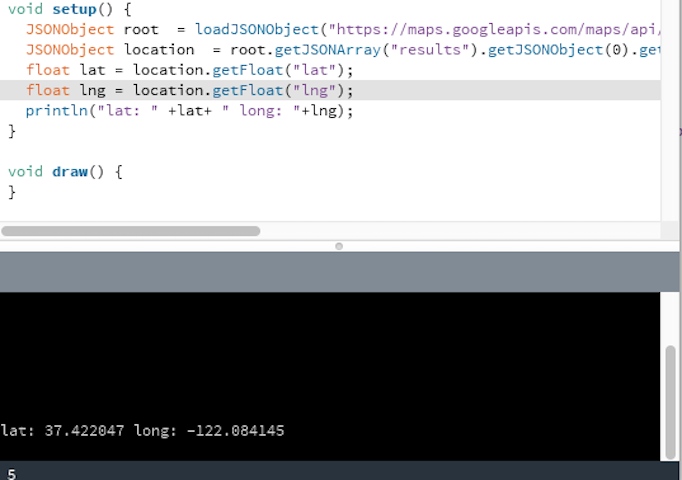
The downside to Forecast.io was that it required, Lat and Long in the API call, which is not good for a user who would rather enter a location in words. So I used Google's Geocoding API to get Lat and Long from a word location.
I then integrated this with the weather call, so that you could set a word described location, get the lat and long from google, and then use that to get weather from Forecast.io.
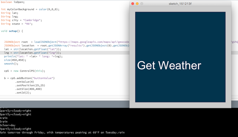
I then added the functionality of location setting into the GUI, so that the user could input and change locations and get weather.
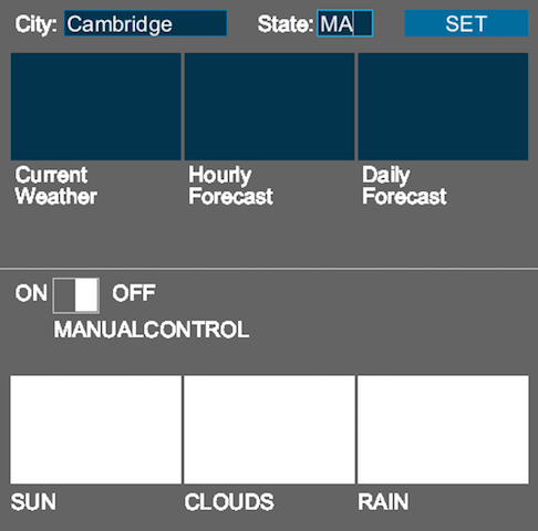
The next step was to tie this into my interface app that controlled the output devices. I created a gui with controlp5, that has two halves. A top half for mimicking weather from a location and a bottom half for manual control of outputs. A toggle switch controls which is active.
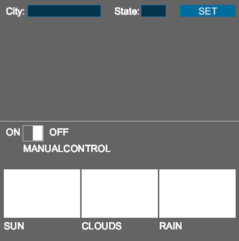
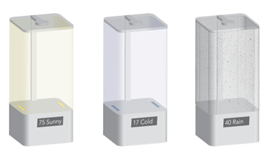
Finally, I added in toggles for the future to the mimicking functionality, so that the user could chose whether to mimick the current weather at a location, todays hourly forecast, or this weeks daily forecast. At this time, only the current weather functionality is working due to time.
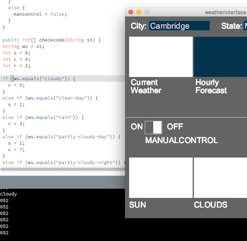
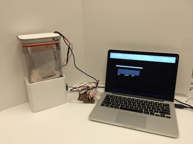
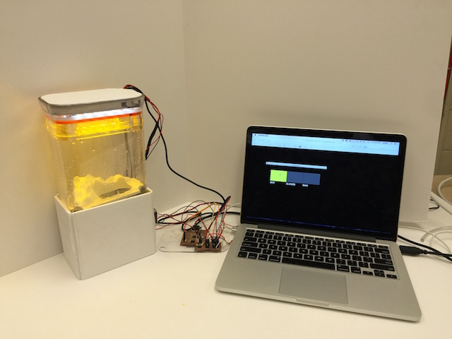
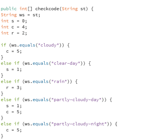
The functionality of the final application is as follows: a toggle switch sets whether you have manual control of outputs or you are mimicking the weather. If you are on manual control each button controls its own output. The program is actively sending data to the microcontroller (0/1 = off/on for Sun/LED, 2/3 = off/on for Rain/Pump, 4/5 = off/on for Clouds/MistMaker). Normally the application is sending all OFF values, but changes and sends an ON value for that device if its button is clicked. If you are on mimicking mode, the user inputs a location and hits "set", then the program grabs the weather data from forecast.io (it also does this every minute on its own from here on out to update the weather). Then the program parses through the weather data and finds the one word description of the weather "cloudy" "clear" "rain" "partly-cloudy". The program then processes the description and for each scenario I have set on/off values for the sun, rain, and clouds. The program then sends the corresponding values (0/1,2/3,4/5) to the microcontroller to mimick the weather. Below is the final GUI and the code is rather long, so you can find it here: Processing sketch.
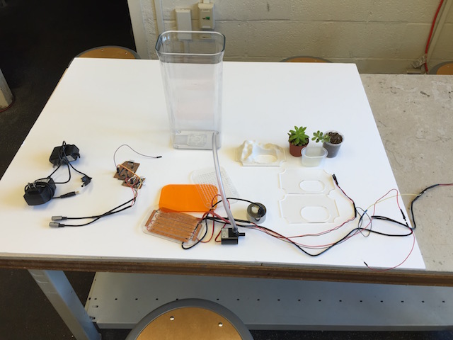
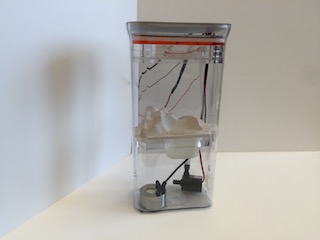
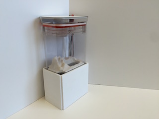
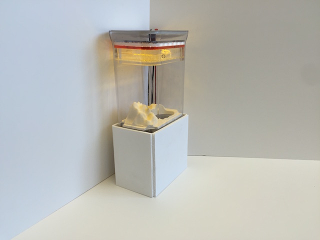
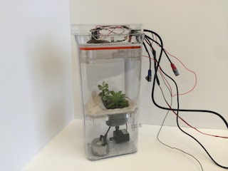
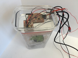
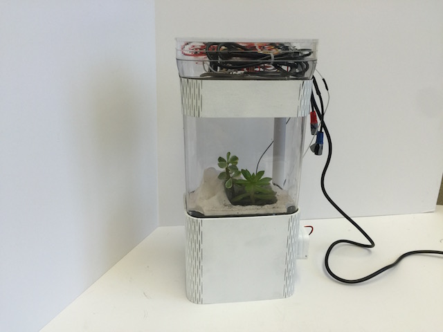
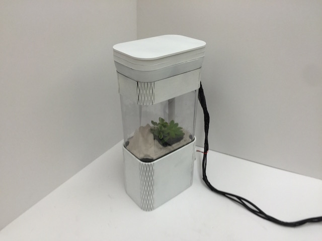
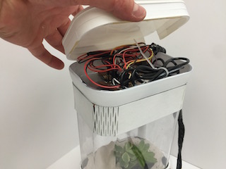
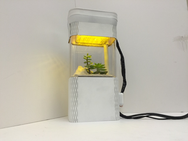
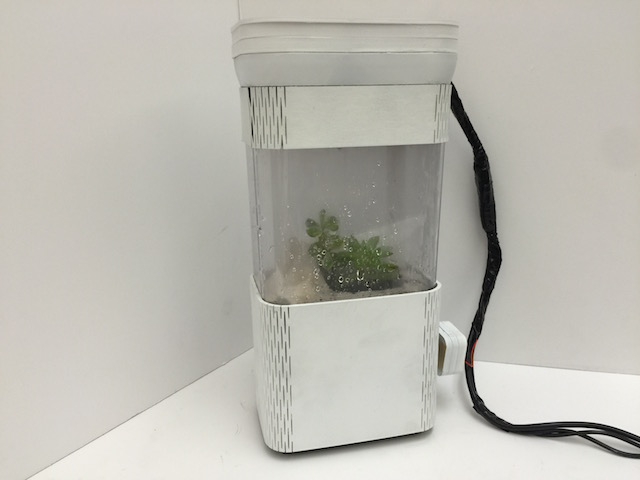
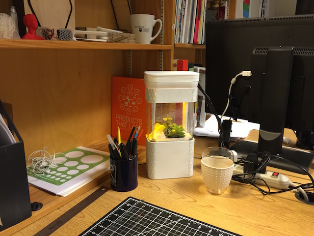
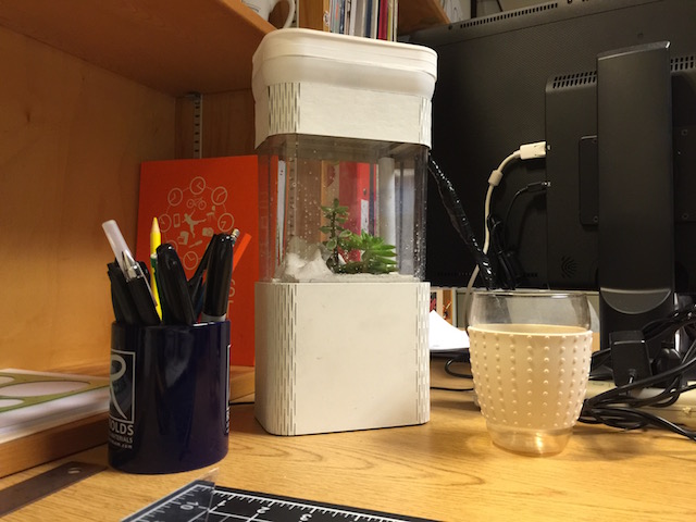
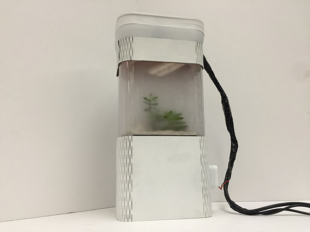
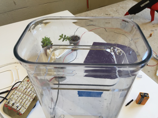
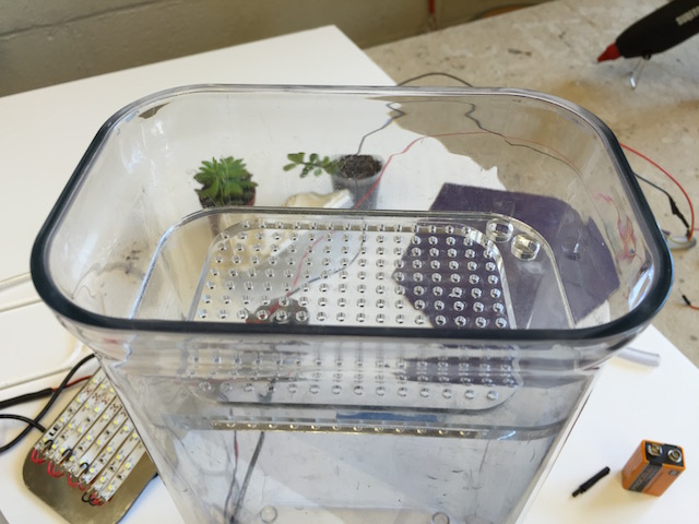
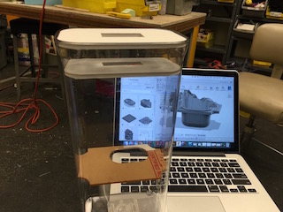
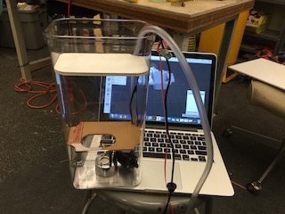
Putting it all together
With all of the modules figured out, all that was left to do was to package it attractively, test it, and continue to make it better. These photos are from throughout my process and document my prototyping efforts, tweaks, improvements, tests, etc...