Machine Building
This week's assignment was a group assignment to design and make a modular machine that makes something. On this page, I will be documenting my contributions, so check out the group page for the full documentation.
Mechanical Linkages for Delta Style Robot
For this project, I was on the team responsible for linking the linear actuators to the end effector. For a delta style robot, this meant designing and making the platform to attach to the carriages, the center platform to connect to the end effector, and the 6 arms on ball joint rod end swivels to connect the two.
After the base team, designed the structural elements to support the 3 linear actuators (given), our team was given the following:


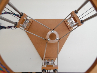
My job on the team was to the design, spec parts, and 3D model the custom components to fill in the center linkages, not seen above, so that the final delta bot would look similar to this:

To start, I talked to a team member Miguel, who had bought a Delta style kit to learn about the linkages, and checked out his machine. On top of this, I did some research online to see common delta style linkages. What was obvious is that center platform had to connect to 6 arms (3 sets of 2 parallel arms) that were linked on both ends with ball joint swivels on rod ends. Miguel's machine used threaded rods and threaded rod ends, so I followed suit.
I knew I wanted threaded rod for the arms and ball joint rod ends for the swivel connections that could then be linked with a screw or rod to the carriage and the center platform. On McMaster, I was able to find 10-32 threaded rod and steel ball joint rod ends with 20 degree swivel that were threaded with 10-32 and had a 3/16" through hole through the ball joint that could be mounted with a 3/16" screw. Additionally, although we did not end up ordering. I found some plastic tubing that could be used over the threaded rod to make it look better.


I sent this off to the group and Eric ordered the parts.
The next step was to design the custom connectors that would allow the arms to connect to the carriages and design the center platform that all the arms would connect to. I designed these parts to be compatible with the materials that we had ordered. So that the ball joint swivels could be mounted to my connectors with 3/16" screws while maintaining full range of swivel movement and keeping each pair of arms parallel.
Caroline sent over the mounting pattern for the carriages to design around.


From here, I went into Solidworks to design the carriage connector. I designed around the mounting pattern and the size of the carriage. On top of this plate connection, I added protrustions with 3/16" holes that will be the connecting points for the 3/16" screws for the ball joint rod ends. I made sure these protrustions were far enough out and were angled to allow full range of movement for the arms. I also decided on having the arms 1.5" apart. I developed 2 versions of this connector. One version would use a piece of threaded rod through all holes. The other version would use screws to mount one ball joint to each protrusion.


After designing, the carriage connectors, I designed the center platform. I used the same protrusion geometry as the carriage connectors and placed three sets of these protrusions on the sides of a equilateral triangle, so that each set of arms would be 120 degrees apart, the same as the linear modules. in the center of the platform, I included four mounting holes that the end effector team could mount to. Once again, I designed two different versions.


To get an idea for how the connection would work, I put together a quick assembly with the ball joint model.

With the models done, I converted them to .stl files so that the rest of the team could 3D print them and assembly them. You can find my files here:
- Carriage Connect V1 SLDPRT
- Carriage Connect V1 STL
- Carriage Connect V2 SLDPRT
- Carriage Connect V2 STL
- Center Platform V1 SLDPRT
- Center Platform V1 STL
- Center Platform V2 SLDPRT
- Center Platform V2 STL
Below you can see what happened to the parts I designed in 3D Printing and Assembly.


