Input Devices
This week's assignment was to design our own board with an input device and read the data from the device into a microcontroller.
Tools+Skills
- Eagle PCB Design
- Modela Desktop Mill
- PCB Assembly
- C (Programming Language)
- Arduino IDE
- AVR Programming
Anduino (Andy + Fabduino)
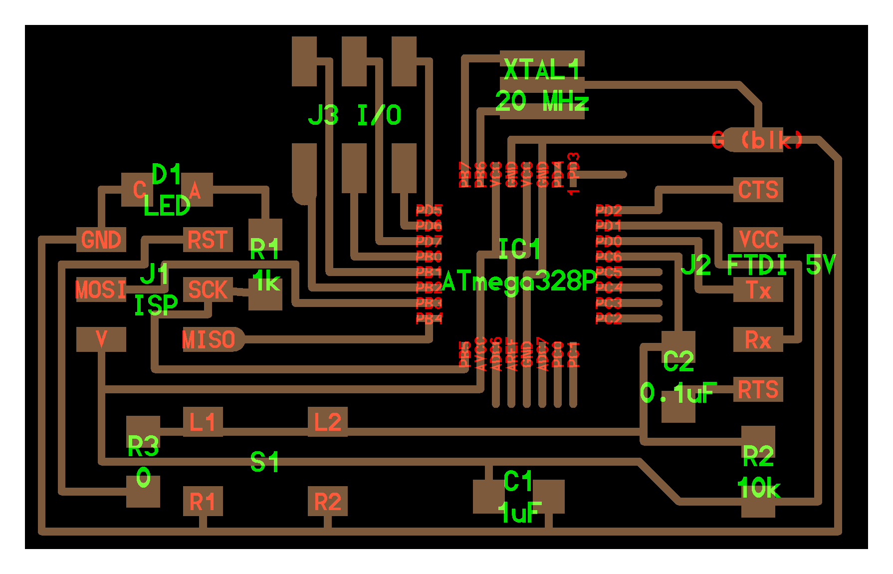
Upon starting this week I realized that the board I designed for output device week would have all the functionality to do input devices, except that I hadn't provided access to any of the pins. So to start this week I redesigned my control board to be my own version of the Fabduino, which I am calling the Anduino.
Unlike last weeks board, this one would be versatile. I wanted to the this board separate from any power regulators, mosfets, and extras for any outputs or inputs. This way I could use one board and just design daughter boards as needed. This is also helpful as for my final project I will be driving 1 5V device, 2 12V devices, and 1 24V device. So separating the different voltages to different daughter boards will be nice. I designed the board similar to last weeks. It is based around a ATMega 328P microcontroller with ISP and FTDI headers for programming and power. However, I scrapped the application specific components and instead added as many header pins as I could so that I could break out boards.
I laid out the board in Eagle and had fun tackling the challenges of how to route all of the pins to headers. With experience laying out the board for last week, this one went a bit faster. I also learned some additional Eagle functionality that made tweaking designs to fit design rules much easier. After some aesthetic touches the board was ready to be milled.


Once again this week, the modela struggled to mill out the fine traces of the ATMega328P with the 1/64" end mill. The first attempt left me with 5 broken, unsalvageable traces. So for the second round I thoroughly cleaned the sacrificial layer, increased my taping, found a better end mill, slowed the cutting speed, and decreased the cut depth. This time around the cut came out a bit better. Two traces were peeling off, but I decided that I would try to fix them.
In the picture below you can see how the board turned out. As you can see, with the broken leads, old soldering irons, and no solder wick for the trick from last week, the solder work was not as pretty. BUT, it worked. I have gotten into the habit of testing continuity between pins and traces and between neighboring pins to make sure everything is connected, but not shorted.

After the tiny traces on the microcontroller, the rest of the solder work went pretty fast!

I connected up the board with my FabISP and the FTDI cable and loaded on the standard blink program to make sure everything was working. It is always exciting to see the LED blink!
Input Device
With the Anduino ready to go, I quickly designed a small daughter board with a phototransitor and button as input devices. I never ended up using the button (my backup), because it ended up not being that hard to get the phototransistor to work.


I once again set up on the modela, relieved that this time I didn't have any small traces to worry about and the milling was quick and painless.


Once again the soldering went really fast, but just a quick note that for all those that are curious the positive side of the phototransistor has a small notch that is not easy to see at first. I forgot to get a photo of the board by itself as I was so anxious to get it hooked up. Below you can see how I connected my daughter input board to my Anduino. My strategy was to have headers for signal pins and a separate set of headers for power and ground. Then I could use a few wires to bring power, ground, and signal to the daugther board.


Using just the multimeter I was able to test the connections and test that the phototransistor changes voltage with varying light. To see the input talking I used Arduino IDE serial communication to read serial out from the microcontroller. I just had to fiddle with making sure that I set up my board to create a serial communication line at the same baud rate as the serial reader (9600 baud). But enough of me talking, lets see it in action!
In the first video you can see the serial communication reading out values 0-1023 from the phototransitor that corresponds to the voltage it is reading. The code I used was adopted from an Arduino example. In the second video, I added a bit of smarts to turn on and off the LED when a threshold value is reached.

As could be guessed, I had set up my board to work with Arduino IDE. I followed Dan Chen's instructions to do this.
This input was just the beginning of my interface application project, so go check it out Week 11
Application Programming