Interface Applications
This week's assignment was to design an interface application to interact with an input and/or output device.
Tools+Skills
- Eagle PCB Design
- Modela Desktop Mill
- PCB Assembly
- C (Programming Language)
- Arduino IDE
- Processing
- AVR Programming
Let's Communicate
This week was all about talking between a microcontroller on a board to an application on the computer over USB serial. I couldn't have done this without a lot of guidance and this week Sparkfun came to the rescue with a really great tutorial!
To accomplish all this I first had to get my microcontroller all ready! For this I used my Anduino which I had already design, milled, stuffed, programmed, set up with Arduino IDE, and tested in last week's input device project Week 10 - Input Devices.
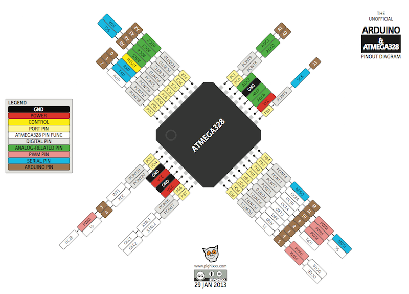
So on the microcontroller side, I used Arduino IDE to write the programs using this handy pinout diagram for the ATMega328P.
Just as a note, I had actually made a series of daughter boards for output devices, but I blew out the MOSFETS, so that part was pretty hacked together. But I figured a small motor and the on board LED could replicate the DC water pump from Week 9 - Output Devices and the LED sun source for my final project.
On the computer side, I used Processing to write the communication program and set up my GUI. This was really nice since Arduino IDE and Processing are both written on the same open source code and share the same look and syntax. For the GUI controls, I used the ControlP5 library to make toggle switches.
The first thing I wanted to do was to try to get my interface application to turn on and off the LED with a toggle switch. Luckily, the Sparkfun tutorial used an example where it turned on and off the LED when you click in a canvas area. The way this works is on the Arduino side you set up the board to read serial in and on the Processing side you set it up to send either a 1 or 0 in serial communication when the mouse is clicked or not. Processing sends the 1 or 0 and the microcontroller reads the input looking for either a 1 or a 0. If the serial input is a 1, it turns on the LED. If it is a 0, it turns the LED off.
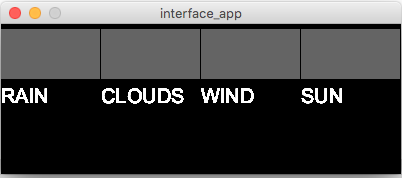
In my interface application, I included some more buttons that I could use in the final project when I want to be able to control rain (water pump), clouds (mist machine), wind (fan), and sun (LEDs). To start I only read the Sun/LED button. The Processing program sends a 1 to the microcontroller when the Sun button is on and a 0 when it is off. The microcontroller then turns on the LED when it recieves a 1 and off with a 0.
Lets Do Two Devices
After interfacing with 1 output device with my application, I wanted to do 2! This turned out to be a bit trickier, because when the microcontroller reads the serial input it only picks up 1 character at a time. So if you want to send two packets of information, it has to record what it is reading in and then figure out what it means.
DISCLAIMER: The way I did it is definitely not the best way to do it (with a buffer), but looking at examples of that seems a bit over my head at the time.
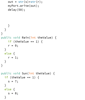
For reference, what I wanted to do now is to still use the Sun button to control the LED, but also control a small DC motor with the Rain button (will be a water pump in the future). The way I did this was to have the application send either a 7 or 8 for on and off of the Sun button (for the LED) and a 0 or 1 for on and off of the Rain button (motor). So for each loop of the program the computer sent a '80', '81', '70', or '71', which the microcontroller read as '8' '0', '8' '1', '7' '0', or '7' '1'. Apparently, it is also sending and recieving '/n' to indicate a carraige return and this can be used to control a buffer, but I just ignored this.
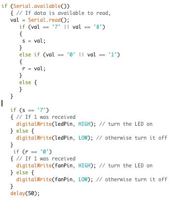
So the microcontroller is recieving a stream of '8' '0' '7' '1' '/n' etc and temporarily storing this. Then I had it check that value, if it was either a 8 or 7 it saved the value to a less temporary parameter that stored the LED value. If it was a 1 or 0, it saved the value to a differ parameter for the motor value (which is labed 'fan' here). Then in every loop, the microcontroller checks these parameters to see whether the outputs should be high or low.
This may not be the most elegant or scalable way of doing this, but it worked!
Interface with an Input
You may be asking yourself, "Andy, you just did an interface application for an output device, are you crazy to do more????" Well yes, I am! Having figured out that I could interface with the output, I now wanted to check out if I could do the same with my input.
This first step with this was to see if I could simply get the phototransistor data from the microcontroller into Processing. By switching the flow of information, I was able to do just that. I could play with the light sensor and read the data into Processing's serial monitor just like I did with Arduino IDE earlier.
I took Sparkfun's example for two way communication, but didn't give it much thought at this point. I just wanted to see if I could get the light sensor data while still having control of the LED. In the example, they had the microcontroller sending a "hello world" while the canvas-click controlled the LED.
Putting it all together
Ok, so the last section was just data not an interface application...Hold on I'm getting there! I knew I wanted to do both input and output with the same application, so the previous was just the first step before I figured out how to both send and recieve on both ends.
To figure this out I followed through with Sparkfun's tutorial. There I learned about the Handshake, where before the real communication can take place first the microcontroller and application had to first exchange one packet, in this case an 'A'. Once this protocol was accomplished, we could go about our business.
Except wait, they can't both send and receive at the same time because there is only one communication line, so they have to take turns. If I understand this correctly, my computer side application was constantly reading data and then sending data in that order in a loop. On the microcontroller side, it was checking the data feed. If the was serial data to read it would read it, but if there was no data at that time it would push its own communication out. I used the serialEvent() call, which is explained here.
So I modified the example and added in my GUI. Now the application would once again have toggle controls for both the Sun/LED and the Rain/Motor, while also reading the light sensor data and plotting it in real time. The way this works, is after the handshake and light sensor calibration the application sends its packets of 8s 7s 0s or 1s as before and then listens for the data from microcontroller. The application knows that after the handshake all of the data from the microcontroller is a number disguised as a string/chararacter, so it parses this input into a number value. Then the application scales a rectangle on the screen to represent the value. (quick note: the best way I found to do this display was to have two rectanges being drawn in the draw() loop. The first is the background rectangle and the second is the data bar which changes length with the light data. On the microcontroller side, it once again reads in the data, sorts the 7s and 8s as LED signal and the 0s and 1s as motor data and triggers the pins accordingly. Then it sends out its light data. The two alternate infomation. (one thing to note here is that any delays from before should be shortened as the alternating information slows this down even further).
What are you waiting for, check out the code! Processing Arduino
Finally, I was able to get it all working and I happily had an interface application that read live light sensor data and displayed it, and also gave toggle controls for two outputs.
Learnings
More than any other weeks, I learned a tremendous amount by doing input, out, and interface applications. I learned to not be afraid of electronics. I became much faster at laying out boards, reading data sheets, finding information, milling, soldering, programming, and testing. I learned about communication. And most of all I become more confident in my abilities to learn and take action to do things!