Molding and Casting
This week's assignment use 3D Toolpaths on the CNC Mill to design and make a positive mold, to use to cast OOMOO 25 silicon into a negative mold, to use to cast DryStone plaster into the positive object.
Tools+Skills
- PartWorks 3D
- ShopBot Desktop
- Solidworks
- Autodesk MeshMixer
- Laser Cutter
- Adobe Illustrator
- Molding (with OOMOO 25)
- Casting (with DryStone)
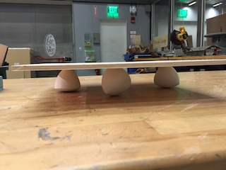
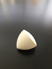
Solids of Constant Width
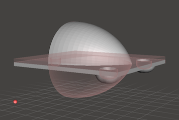
In deciding what to cast, I wanted to make an object that I wanted more than one of, so to use the full benefit of having a mold. I chose to model and cast a solid of constant width. They are essentially non-spherical solid objects, that are always the same width between two parallel planes. I could explain more, but this animation should do the trick:

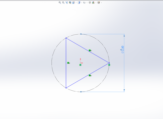
The Solids of Constant Width that I've seen are based around a Reuleaux Triangle, which is a 2d shape of constant width.
To design the Reuleaux Triangle, I used Solidworks first to sketch out an equilateral triangle and then used the three point arc two to extend arcs around each of the edges, where the opposite vertex is the center of the arc and the verticies of the edge are the end points. This creates a Reuleaux Triangle.
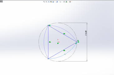
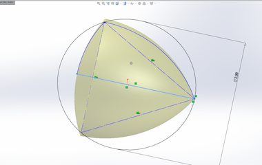
In order to create a solid of constant width from this triangle, I revolved the shape around a symetric axis. I came across another solid of constant width, called a Meissner Tetrahedron, which is a Reuleaux Tetrahedron that has been modified to become a solid of constant width. I will consider making this shape in the future if there is more time.
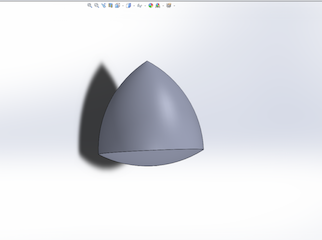
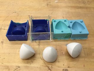
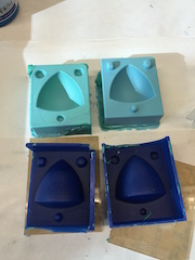
With the solid constructed, I wanted to make two opposing molds, so I split the model along a symetric plane and added keys of varying sizes and shapes. I then created the two halves of the mold by keeping solid keys and the one half of the solid, connected by a thin planed surface on one side, and shell offsetting the keys for the other half. This way I could guaruntee the two halves of the mold would match accordingly. I exported the files as .stl files and used Autodesk MeshMixer to check the surfaces and make sure the two halves would machine well.

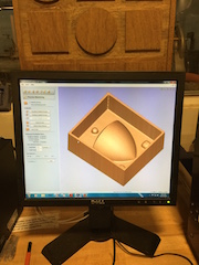
I set myself up on the ShopBot desktop, and used PartWorks3D to do my 3D path planning, first with a rough cut to remove material, followed by a finish cut for good surface finish. I ended up being the first in the class to use the machine, so I gladly learned the lessons for everyone. I had some problems with getting the correct zeroes for the tool and also lost a couple walls of the mold.
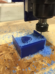
Despite the broken walls, the features themselves came out great, and I was able to repeat the process for the second half of the mold. Since I had broken walls, I knew I had to make gates for the sides to keep the silicone in as it dried. I went quickly into Illustrator and used the lasercutter to cut out some tight fitting, press fit walls to surround my molds. I used clay putty to fix up some holes and make sure I got the shape I wanted.
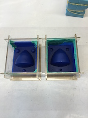
With the molds ready to go, I mixed up a big cup of OOMOO 25 (note to future users: do not attempt to mix a big cup all at once, you wont get a good mix) and poured my molds. After some emergency remixing and repouring, I was able to fill the molds with the OOMOO. I let the molds solidify over the weekend and was pleasantly surprised to find that even though I had not achieved a good mixture, the silicon molds came out just solid and showing my solid features nicely!
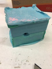
I bundled the two halves of the mold together with rubber bands and cut a small sprue in the top to pour the plaster. I mixed up a batch of DryStone plaster to the consistency of pancake mix and began pouring it into my mold. It was now that I realized that my sprue was too small and not allowing the material to flow freely into the mold. Rushing against the pot life clock, I opened the sprue a bit more and slowly poured the DryStone slurry into the mold until I was satisfied. I then left the mold to dry for a few hours.
Four hours later, I returned and opened up the mold. To my surprise, the mold had a very nice surface finish and no bubbles in the surface. There was, however, a very noticeable parting line that I did not like and the sprue attachment location was rather large.
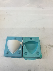
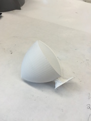
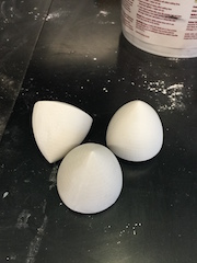
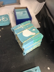
Using some sandpaper, I was able to smooth out the defects and I was left with a very satisfying solid of constant width! Now to make two more!
This time around I make the sprue a bit wider and made it more funnel like. In addition, I made the DryStone slurry a bit less viscous in hopes that it would flow into the mold easier. In my rush, I forgot to degas the slurry in the vacuum chamber this time. I left the mold bundled up for round 2 a bit nervous that I will have bubbles or that my more liquidy slurry would cause problems. Time to wait 4 more hours.
Object number 2, came out solid, but with some clear bubbles towards the top of the mold. I tried my best to prevent bubbles for number 3, but they appeared in that solid as well. Somehow I had my best pour on my first try.
Now that all three were all casted, I sanded down the parting lines and sprue marks and anxiously tested them. Overall, they are really great models of a solid of constant width. There are slight variations in one from another and so they don't always roll perfectly in sync. However, when you apply pressure and make sure you have a perfectly flat planar object, you get pretty good results!