Embedded Programming
This week's assignment was to use our FabISP devices from Week 3 to program our ATtiny44 microcontrollers on our FTDI boards from Week 6.
Tools+Skills
- C (Programming Language)
- Arduino IDE
- AVR Programming
Flash the Light
Given the good examples and tutorials online, I knew I wanted to start this week at the basics, by following some basic examples of programming the ATtiny to flash its light when its button is press. For the examples I used past tutorial give here. These tutorials go over three different ways to write the C code for the microcontroller.
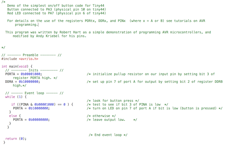
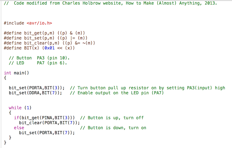
The first example is a very simple code that writes the instructions as prescribed by the ATtiny44 datasheet. Essentially, the code sets the input pin where the button is connected to HIGH and waits until it to drop LOW, which indicates a button press. Then the microcontroller switches the pin attached to the LED from LOW to HIGH. I had to adopt the code from the example to fit the the input and output pins that corresponded to the button and LED setup on my board. I was able to accomplish this by following the information laid out in the ATtiny44 datasheet.
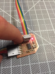
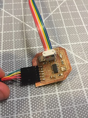
I then connected the boards two boards each to their USB sources and connected them to each other via the six pin ISP connector.
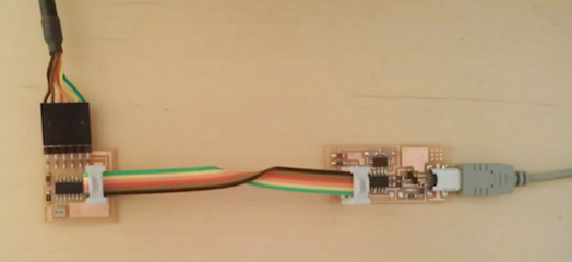
To program the board with my modified C code, I installed AVRDude and followed the instructions seen visually here. The programmer used the .make file to install the .c file onto my ATtiny44 microcontroller and program successfully worked to turn the button on and off with a press of the button.
I then moved onto the next example, which this time uses macros to make the program more user intuitive. This made it much easier to describe the input and output pins numerically and also turn on and off pins with 'set' and 'clear' calls. This began to feel much more similar to the Arduino style code I was familiar with. In the video below, you can see the entire process and the result.
Once again, the programming was easy and the board worked as anticipated, so I moved onto the third example, which goes another level up and makes the code even easier to change and read by declaring variables.
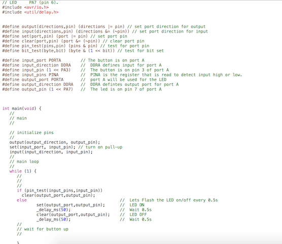
To spice things up, I decided to modify the code to blink when the button was pressed instead of just turning on solid. To accomplish this I had to install a new library that defined a delay function. I then modified the code accordingly and programmed it only my ATtiny44. Below you can watch the video of the process.
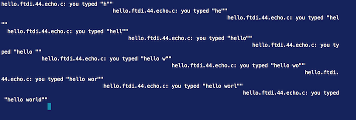
Now that I had a good understanding of how to program the board, I decided to try another example. So I decided to try to setup my board with the EchoHelloWorld program that Neil Gershenfeld describes here. In this case, the board is not just working locally between the board and the components, but it is not communicating with the computer over USB/FTDI. The program for the board to read keyboard strokes and echo back what you are typing. After struggling to figure out how to read back the serial communication from the board, I was finally able to replicate the Hello World Echo.
Having figured out the Echo and the button, I wanted to combine the two. This time I wanted to program the board to turn on the light every time the letter 'b' was typed. To do this, I modified the keyboard stroke reading loop to look for the letter 'b' and turn on the LED pin when it was typed and turn off / stay off when any other letter is typed. The results can be seen in the video below.
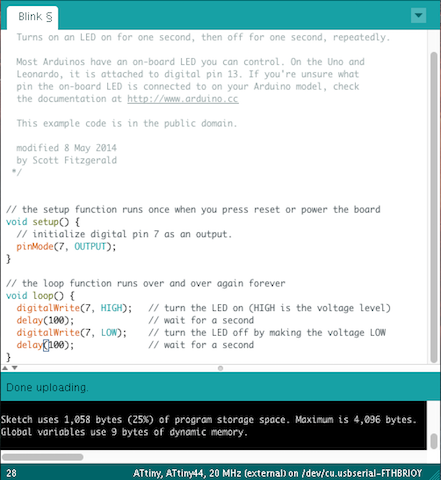
All of the previous examples were done in C and using AVRDude to load the code through a command line interface. Having experience using Arduino IDE in the past, I was excited to get to interact and program the board in a familiar manner, so I decided to try to use the Arduino IDE to program the ATtiny44. For this I used a great tutorial from here. Using the ATtiny board manager from David Mellis that you can find linked on that page, I was able to use the Arduino IDE easily as the interface for programming the ATtiny44 on my board. I have found that the work flow is much faster for me and I prefer working with the familar interface.
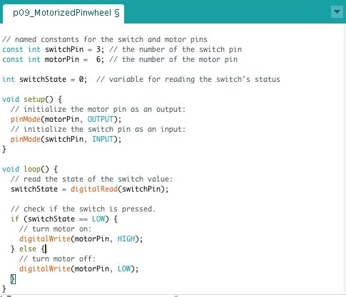
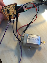
Finally, I wanted to drive a motor, so I found a DC motor that would work on 3.3V from the FTDI cable. I decided to use the pin headers from the ISP 6 pin connector to repurpose as pins to drive the motor. So I repurposed the Pin 6 MOSI pin as my output power signal from the board to the motor and used the ground pin to ground the motor. I adapted an Arduino example code so that the motor would turn on when the button on the board was pressed.