Output Devices
This week's assignment was to design our own PCB around a microcontroller to control an output device such as a motor, stepper, servo, speaker, or LED array.
Tools+Skills
- Eagle PCB Design
- Modela Desktop Mill
- PCB Assembly
- C (Programming Language)
- Arduino IDE
- AVR Programming
Lets Make a Fountain
I knew that my final project will most likely involve a couple different output devices. A water pump to pump water up to a reservoir, a mist maker to make clouds, and LEDs to create lighting affects. So for output devices I wanted to make sure that I could figure out how to control them. First, I had to order them, which took longer than expected and delayed this week.
While I was waiting for the parts, I designed my board. Unfortunately, the mist maker, water pump, LEDs, and microcontroller all work on different voltages. I know in the future I will have to integrate all, but for this week I chose to just work on 12V for the water pump and 5V for the microcontroller.
I knew that with just one device I could make a simple board to do just what it needs to do, but I knew looking forward that I would have to graduate from the ATTiny44 up to a board with more pins. So I jumped up to the ATMega328p. I loosely designed my board around example designs for the FabDuino, Neil Gershenfeld's 12V motor board, Neil Gershenfelds output speaker board, and a water pump PCB from off the internet.
In comparison to previous weeks, I had many questions and doubts about using new processes and components. Such as using the 12V-5V regulator to have two different voltages on the board, using a transistor as a switch to control a motor, laying out a board from scratch, using a new microcontroller, and soldering smaller and tigther pins on the ATMega.
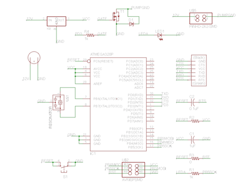
As I explained earlier, although I didn't utilize nearly enough of the pins, I designed around an ATMega328p Microcontroller, which is the larger package that can be found in the FabDuino design. This provides a lot of access to input and output pins. Following the FabDuino design, I added a LED and button for debugging, reset, and simple interface. Additionally, I followed the FabDuino design for resistors, capacitors, ISP headers, and FTDI headers. Although, I am still not entirely sure on how to determine the correct value for these components, I am beginning to understand the reasoning for their placements. To power the board with 5V, I used a 5V voltage regulator to step down the 12V provided by a voltage generator that is required for the water pummp. To control the pump, I provide the positive side with the 12V straight from the voltage source and use a transistor on the negative side of the pump motor as a switch. A pin on the microcontroller controls the gate pin on the transistor which selectively allows current to flow through the transistor.
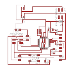
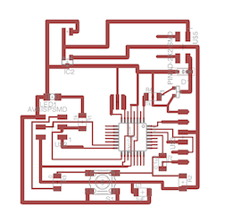
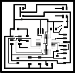
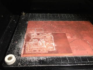
With the schematic figured out, I designed the board layout and traces. Once again loosely following the examples, but also doing some original layout. I then decided to widen all of the traces that I could to decrease trace resistance, especially on the ground and 12V traces. I then exported the board traces and outline and cleaned up the png files with photoshop to get two complementary trace and outline files that fabmodules can use on the Modela.


I set up on the Modela and although the first cut attempt was messy due to an old end mill, the board came out quite nicely the second time. I cleaned off the board carefully and tried to repair some traces that had been ripped off by the milling process. I found the small traces for the ATMega pins to be easy to break.
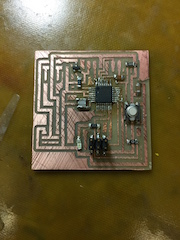
With the board ready to go, I soldered all of the components on to the board. I was a taught a trick to deal with the small pins on the microcontroller to add a lot of extra solder and then wick it off. Surprisingly this worked really well. I checked continuity with the volt-meter and only had to fix up a few connections. Having had a slight incident between my thumb and a kitchen knife this week, soldering was a slow and tricky process this week.
I tested the board by first loading the classic blink code that is common to Arduino devices. Since the board had many FabDuino components, I thought this to be an appropriate test. I was once again surprised at how easy and satisfying it was to get the board programmed. I next tweaked the code to turn on and off my output pin that drives the transistor.
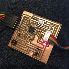
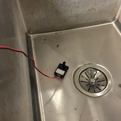
Even though the board was running only on 5V, I decided to do a preliminary test with the pump. So I hooked it up and found out that it worked just the way I wanted it to (although at lower power, so the pumping ability was diminished).
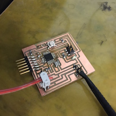
The next day, I took the board into the lab to hook the board up to 12V on the voltage regulator. Now my pump would be driven on 12V as intended. I hooked it all up and was once again pleasantly surprised that everything was working as intended! The pump turned on and off with the microcontroller output pin and created a good fountain display.
Overall, I learned a lot this week about board design, motor driving, and electronics. Most of all, I gained a lot of confidence that perhaps electronics design isn't as scary as I think it to be and if I read the manuals I can actually trust the devices to work as advertised!