Rhino/Grasshopper | Partworks3D | Shopbot
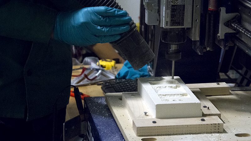
I actually spent this week desinging a large installation made of 3D printed glass. It will be a 3 meter high column of varying surface topology, but in truth, it will take another year to build. To fulfill this week's assignment I've chosen to use the Shopbot CNC mill to fabricate a critical part for the production of the glass column. Having used the machine to mill constructions from large sheets of plywood-namely, this 'foot' for Mediated Matter's Ocean Pavilion installation, which uses more than 80% of a 4 foot by 8 foot half inch sheet of birch plywood-I also chose a part which would let me explore different milling techniques. I designed and fabricated a two part, flip-milled, housing for heating elements used to control the extrusion temperature/viscosity in the glass printer. And to make it a little more interesting, I used a refractory ceramic fiber composite, a material for which we had to calibrate the machine controls. In the future this may be made of a castable ceramic material as well.
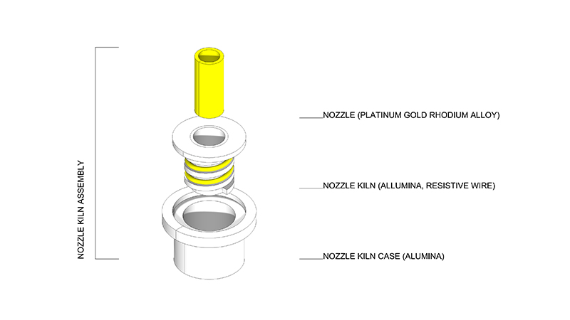
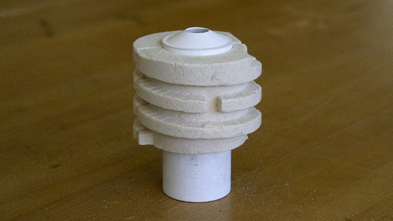
To prevent the glass nozzle from coming into contact directly with the resistive heating elements, the printer needed a housing to separate the two componenents, essentially a ceramic sleve with grooves to hold the heating coils. This could remain in the printer, while the nozzle is easily removed or replaced. It is one of many steps towards complete modularity for the glass printer.
Initially, I used grasshopper and rhino to design the part with only a few given parameters. These would be inner diameter, wall thickness, diameter of the heating element coils, the requisite length of the coiled element (power output is dependent on resistance which is dependent on the number of coils, something that needed to stay constant), the height of the part. I ended up using a linear optimization algorithm (a plugin for grasshopper called goat), to vary the pitch of the element groove helix to get as close as possible to the right length
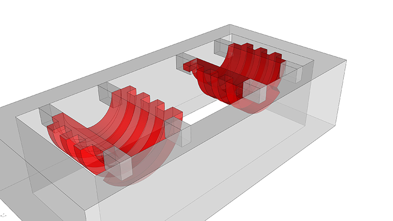
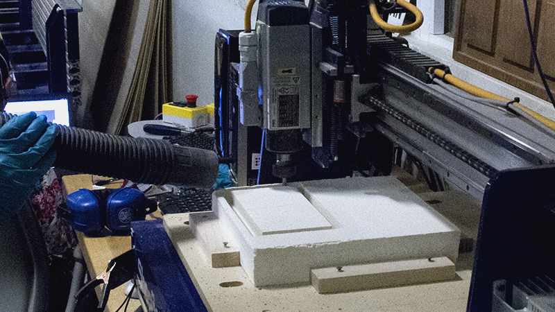
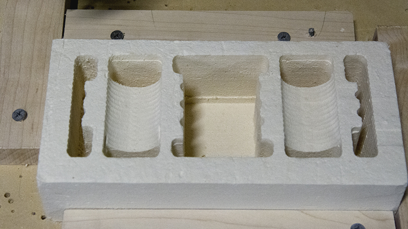
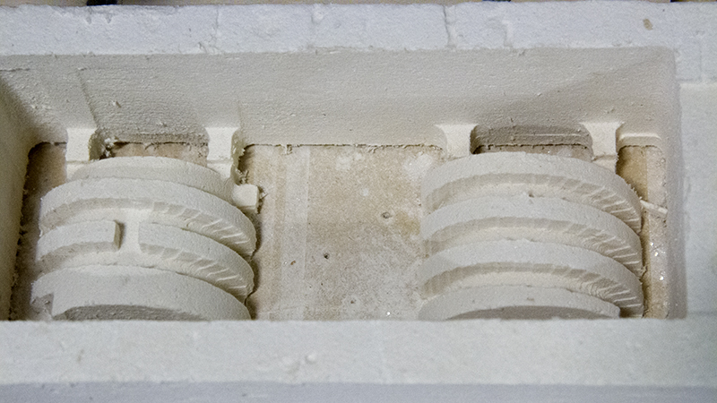
Next, the model was split in two and place in a symmetrical box, once with the interior facing up, and once with the exterior facing up. These were exported as stl files and I used the vectric partworks software to make toolpaths for the Shopbot. To ensure we had a symmetric 100mm by 200mm block of material, a block was milled with the shopbot. A jig of 4 off cuts of wood was also used as a fastening system. Rough and finish cuts for the interior took a little over an hour. The block was flipped to mill out the other other side. The finish cut for the helical grooves on the outside was one hour on its own, but to fantastic effect.
The final two piece fixture is shown, fitting snuggly around the nozzle, ready to go to the glass printer.