Final Project : The Bike Helmet
Idea
When commuting with my bicycle at night, I feel almost invisible, and very unsafe. Also, many time I find myself hoping I could signal the cars and riders around me that I am about to stop or turn. These reasons are what made me make my smart bike helmet, I also thought that this helmet could be a great integration of all the different things I learned through the semester and a way to learn some more.
Design
I was inspired by the cardboard bicycle made 2 years ago in Israel. If you can make an entire bike out of cardboard and ride it safely, could you make a eco friendly helmet to fit?
I then found out that someone already thought about this before me - Kraniums and they are selling a cardboard helmet that has proved to be safer than some rigid foam helmets.
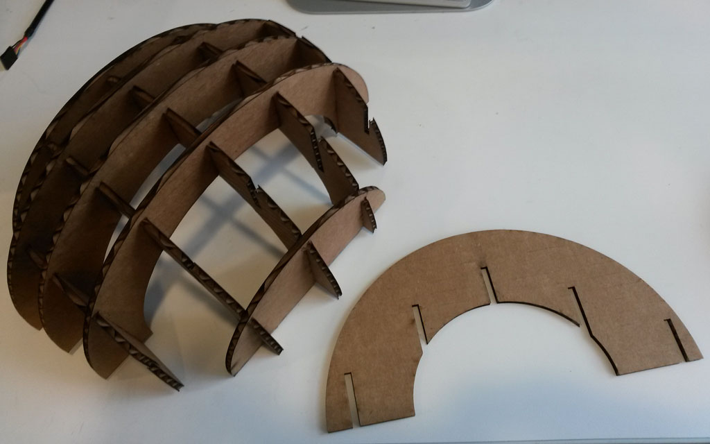
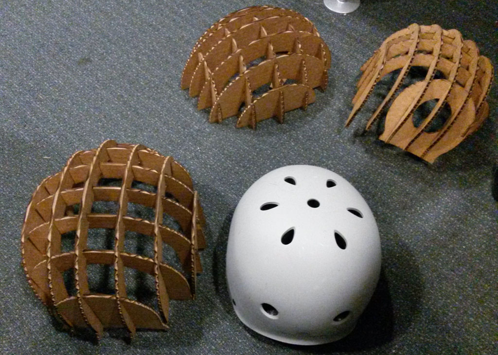
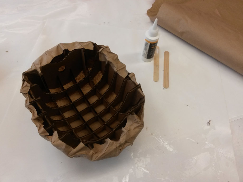
This led me to the decision that the skeleton for my helmet will be laser cut cardboard - it is light, safe, and easy to make.
I measured my head and as a first test made an half ellipsoid and cut it out. this worked great, so I used Rhino to design a nicer looking helmet.
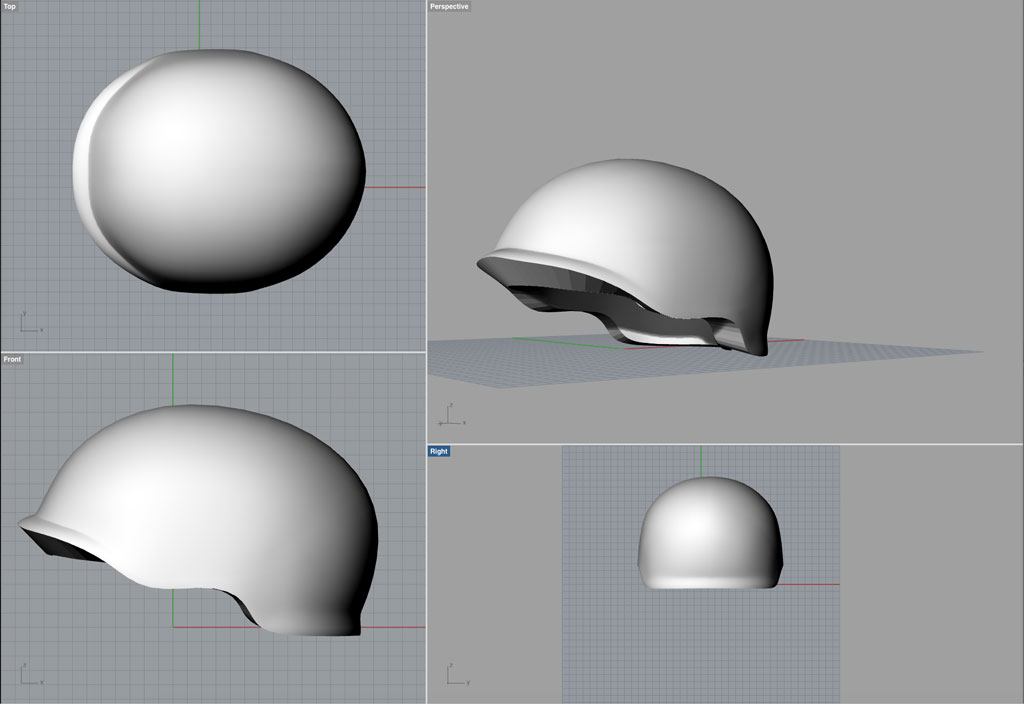
I used a great Grasshopper script I found here to create waffle construction.
Making The Helmet
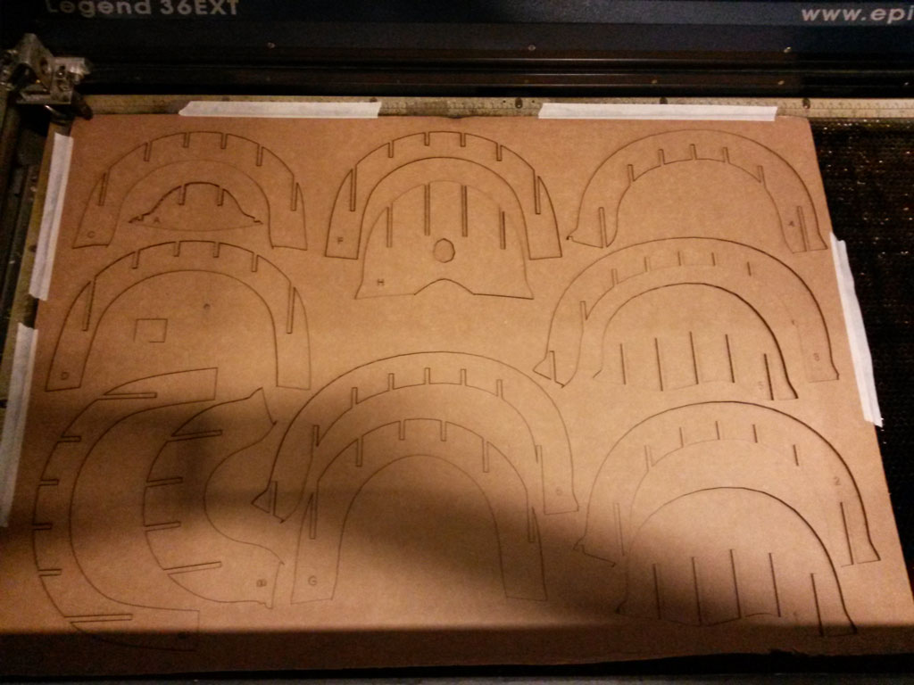
I started by laser cutting cardboard.
After construction the helmet together and trying it out, I decided I need to make a rigid top for it.
I first decided to try composites. This is explained more on composite week page (added soon).
Here are some pictures of the process:
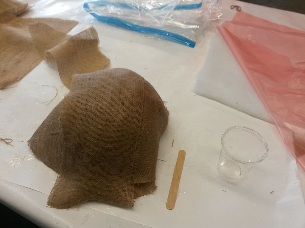
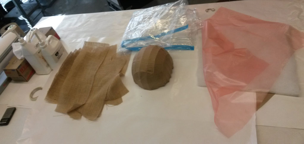

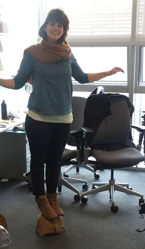
The result was a really strong helmet (I could even easily stand on it, as seen in the pictures above) but I did not like the look of the burlap, and also wanted a cover that is clear, so I can add the LEDs under it.
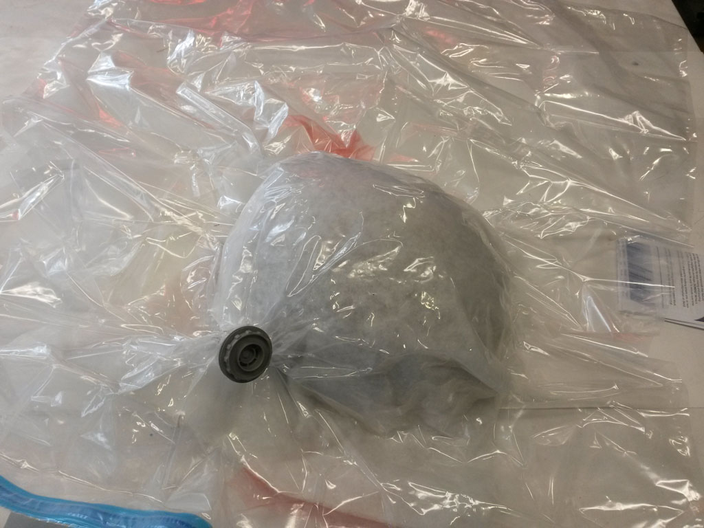
As an alternative, I tried to do vacuum forming.
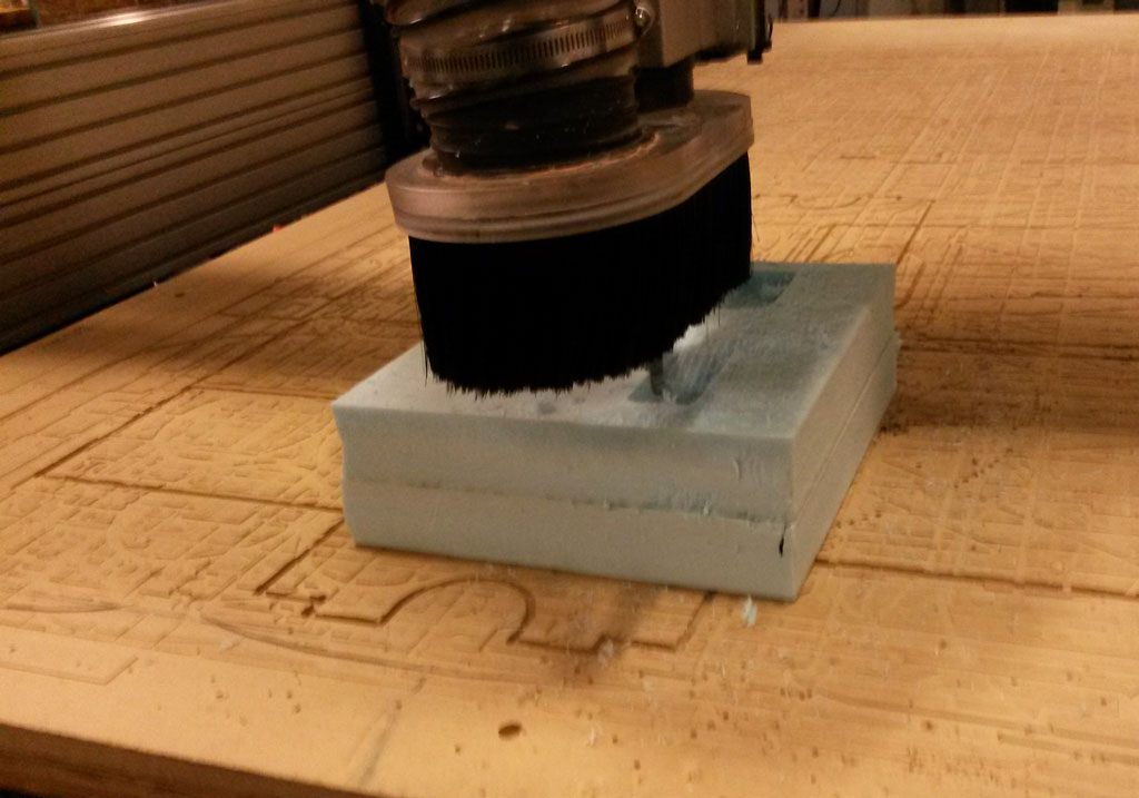
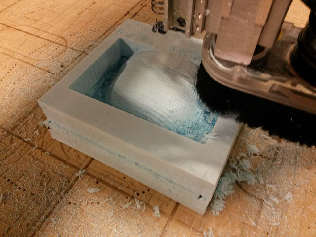
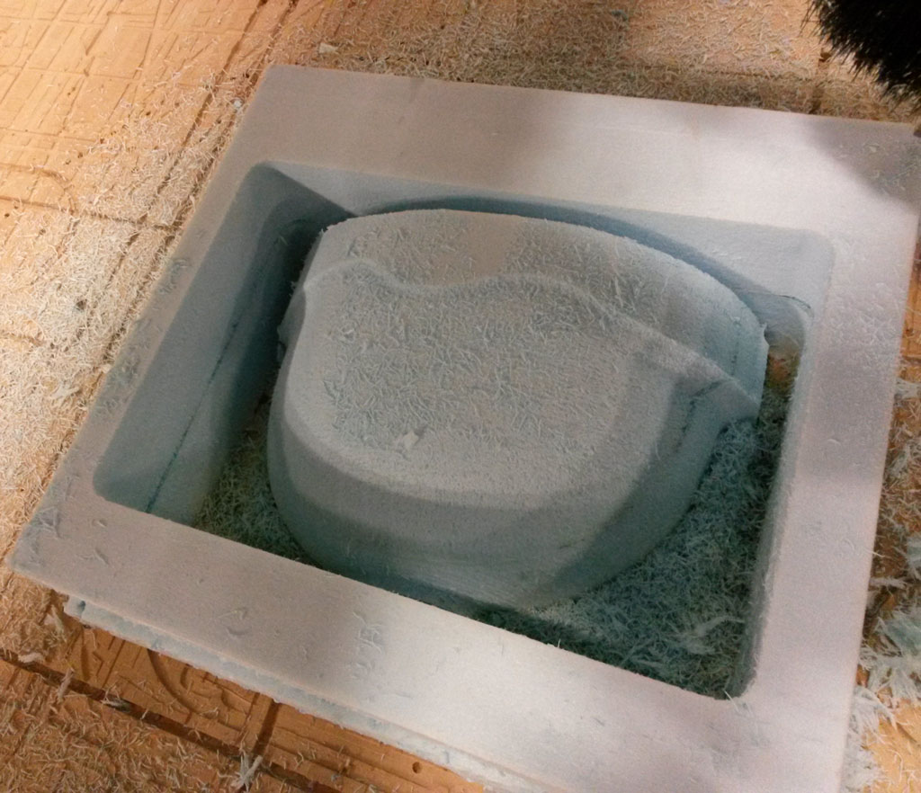
For doing vacuum forming, you need to have a mold. Since I wanted to use thing that were in our inventory, I decided to CNC foam. The largest tool head in the shop that could mill the foam was 5” long. So I had to cut my model in half, and machine to pieces of 4” foam. (I glued together 2 blocks of foam using super 77 glue).


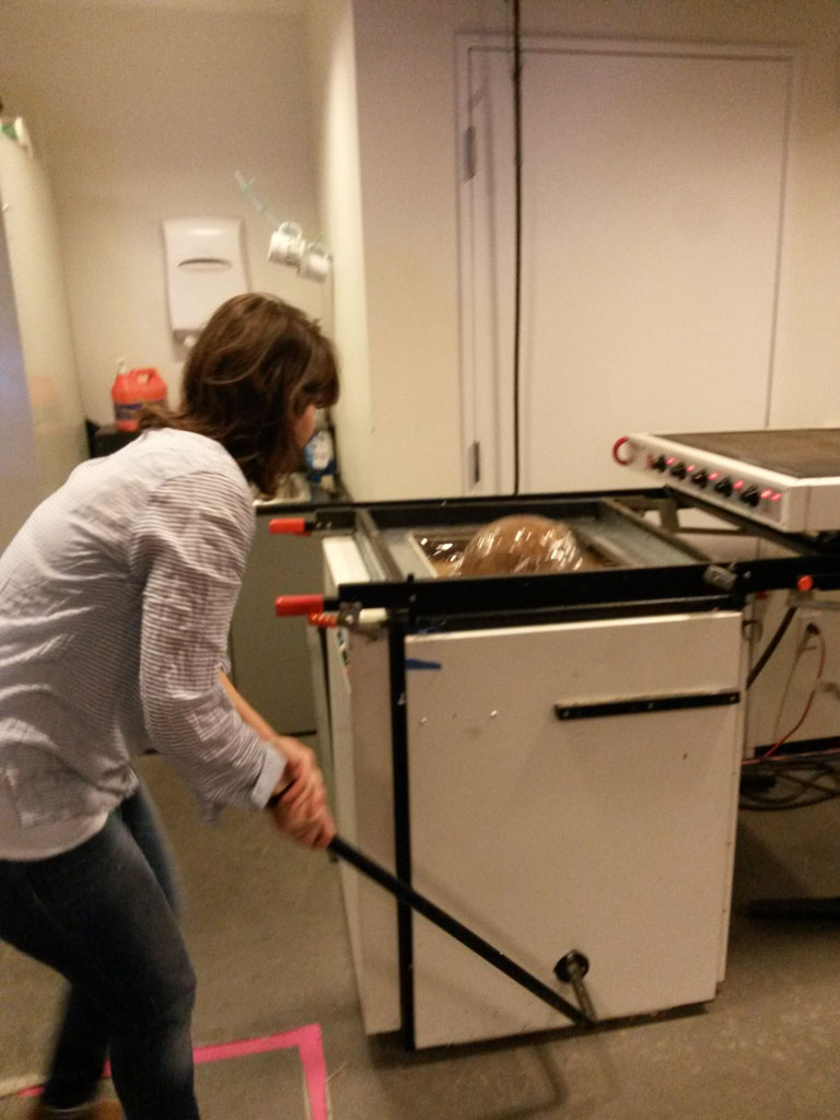
Vacuum forming is a really quick and simple process, but it take time to master it. John and Tom helped me a lot.
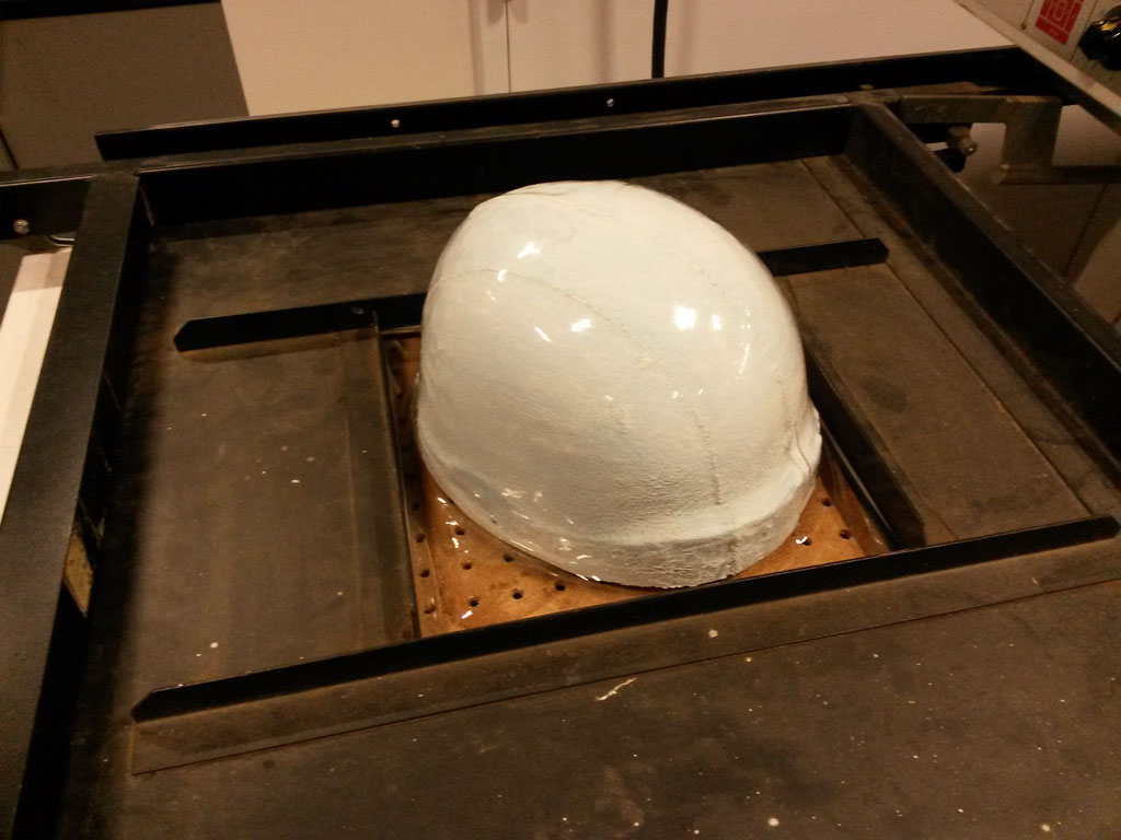
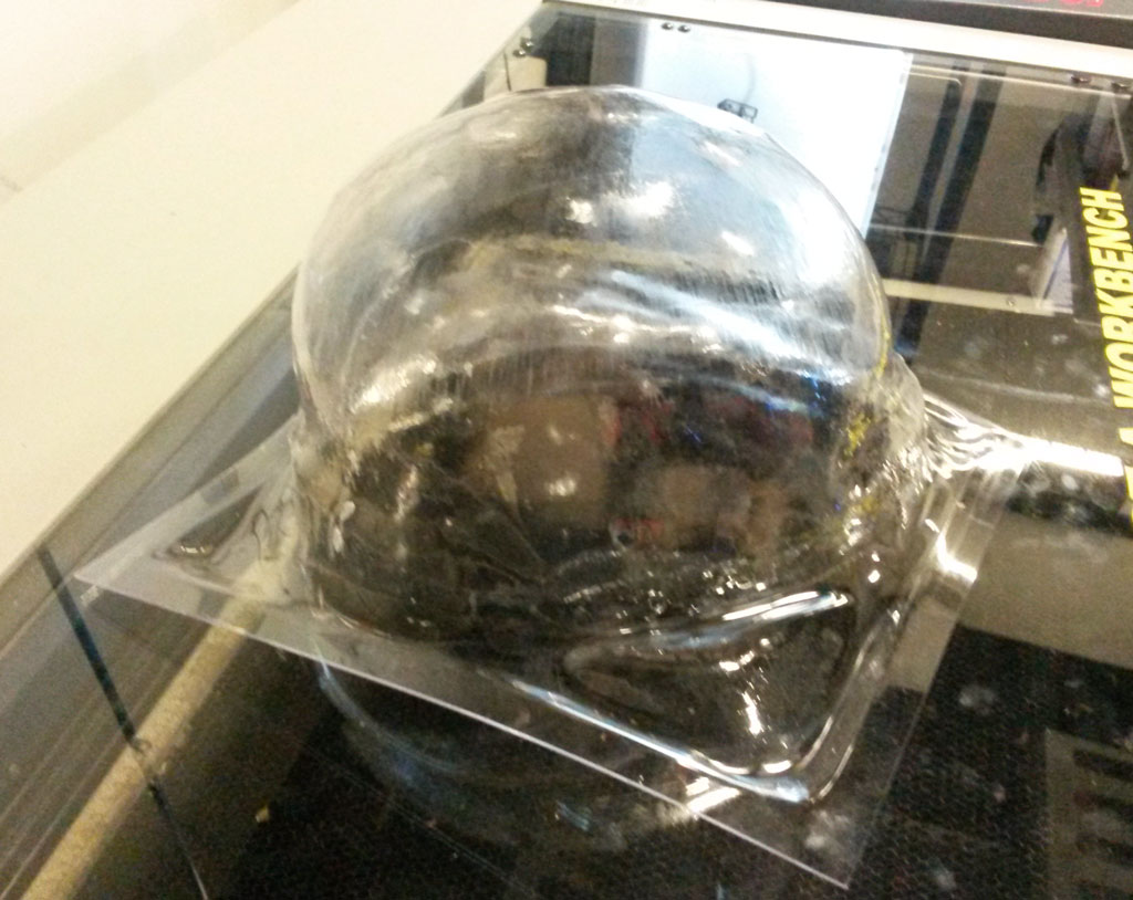
The process starts with heating up a piece of PTEG plastic, placed above the mold, when it’s hot enough, usign a lever, the model is pulled up against the plastic and the vacuum is turned on so the plastic will get the shape of the mold.
The hardest part is knowing exactly when the plastic is ready. If it’s not hot enough it will not be pulled all the way on the mold. If it’s too hot, it become too wide, and you get wrinkles and a mess. The difference between not hot enough and too hot is a matter of seconds.
Another thing we’ve learned is that vacuum forming on foam is not the best Idea, because the foam gets hot, changes it shape and stick to the plastic.
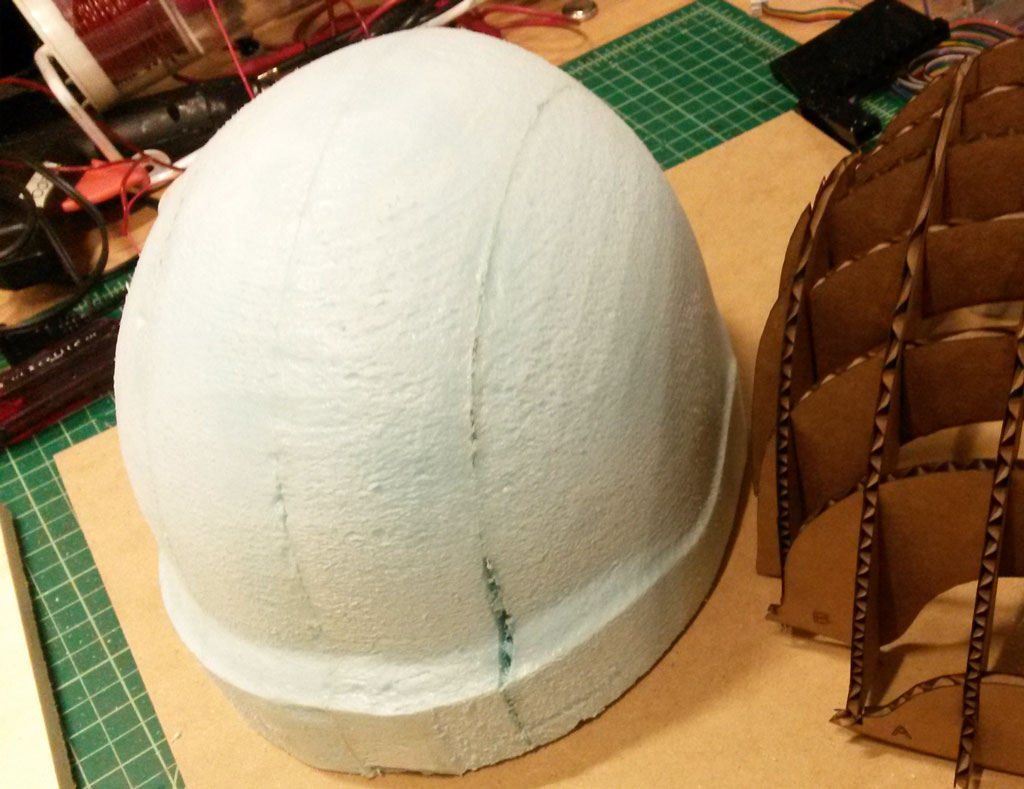
In order to prevent it from sticking, I covered the mold with Gesso and let it dry, I then sprayed a lot of release spray on it before every vacuum forming.

I did not consider the shrinking of the foam during the vacuum forming. This was a problem since the plastic helmet was too small and could not fit on the cardboard. For the plastic to fit on the cardboard and the cardboard to also fit on my head, I had to make the cardboard model really thin. In my original design the offset between outside and inside was 3cm, to fit inside the plastic, I had to change this offset to be 1cm, I only wanted to use this option as a last resort, since it would make a pretty fragile helmet.
I tried to vacuum form again, this time on a cardboard model.
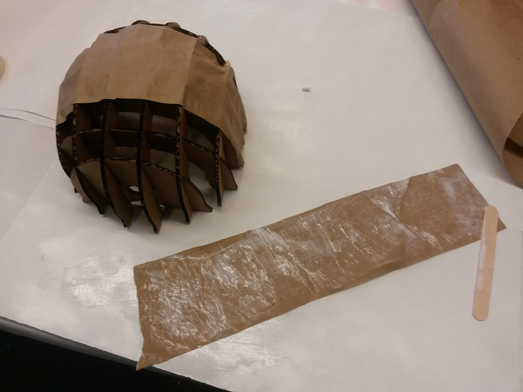
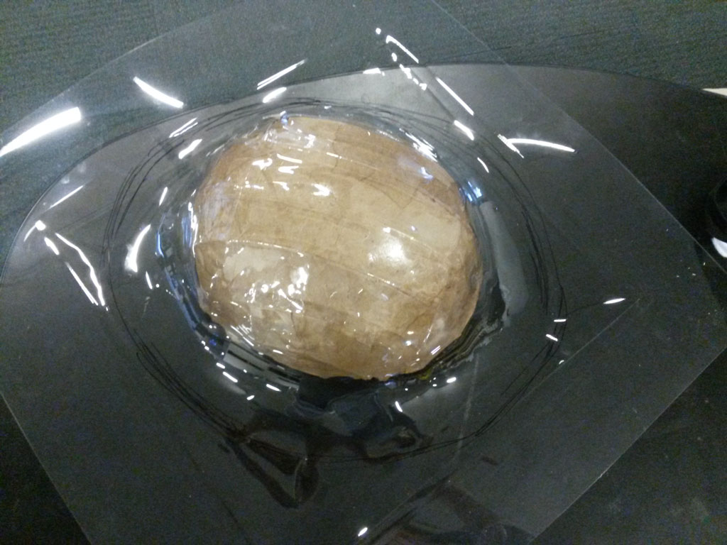
I used paper mache to cover the helmet from the outside. Since I already used this technique for the composites, I knew the paper with the glue will be strong enough to handle the vacuum forces.
I cut brown paper in pieces, and glued them on top of the helmet using All-purpose glue that I mixed with a little bit of water. it’s very important that the entire piece will be covered in glue.
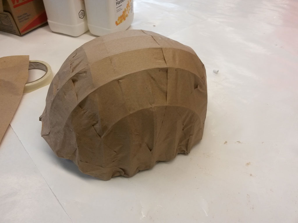
I again sprayed a lot of release on the model.
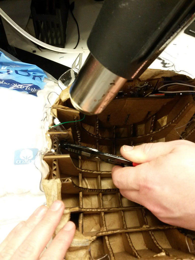
I tried the cardboard mold twice, the first time, it was just a little bit too cold and did not go all the way to the edges of the mold. The second time it was way too hot, it sticked to my model and I had to throw it away. I took the almost perfect one and later used a heat gun to fit it completely on my cardboard base.
Electronics
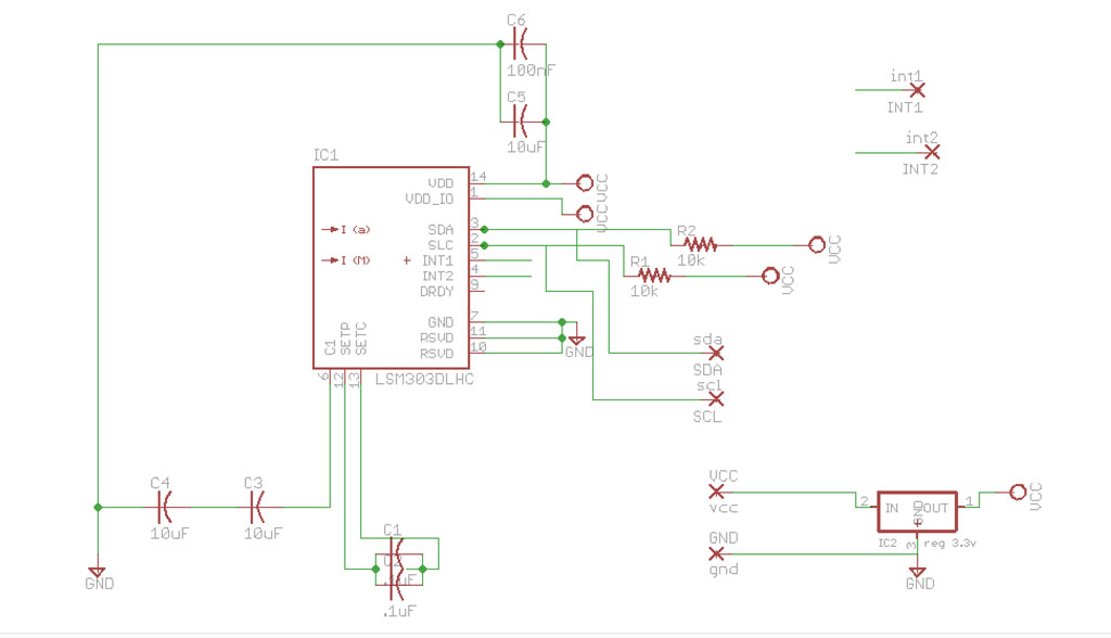
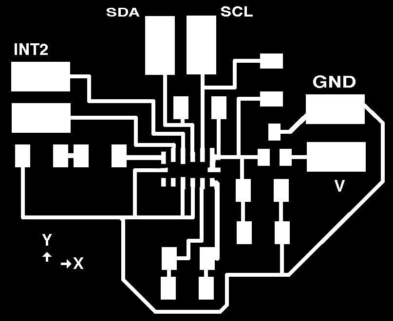
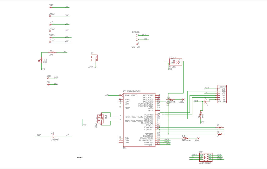
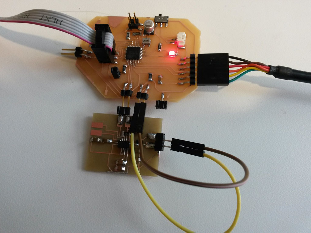
The electronics part was done in parallel to the making of the helmet itself. I started out by making a small breakout board for the LSM303 - The accelerometer and compass sensor. I thought that having a compass in my helmet could be useful for other cool implementations and wanted to try it out.
I used the Application hints from the LSM303 datasheet.
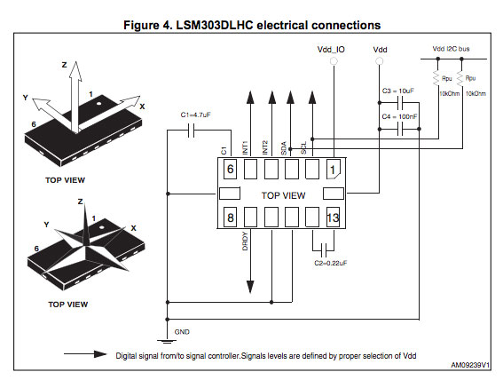
Since we don’t have 4.7uF and 0.22uF capacitors in the inventory I used two .1uF capacitors in parallel to get .2uF, and two 10 uF capacitors in series to get 5 uF. I designed the board in Eagle leaving large SMD pads to connect power, GND, SCL,SDA, INT1 and INT2.
I also added a 3.3V regulator (Analog supply voltage 2.16 V to 3.6 V specified in the datasheet).
I used Neil’s reflow method to solder the tiny accelerometer component.
I then tested this using a Sparkfun RedBoard (Arduino Uno compatible) and Adafruit’s LSM303 Library.
At the first try, nothing printed to the serial port and I was very disappointed. I tested the board using a multimeter and everything seemed fine. One of the TA’s suggested that the accelerometer is not soldered to the board correctly. I used to heat gun again and pressed the component the the board really hard this time, from all it’s sides.
This did the trick and this time I got values printing, corresponding to the location and acceleration of the board :).
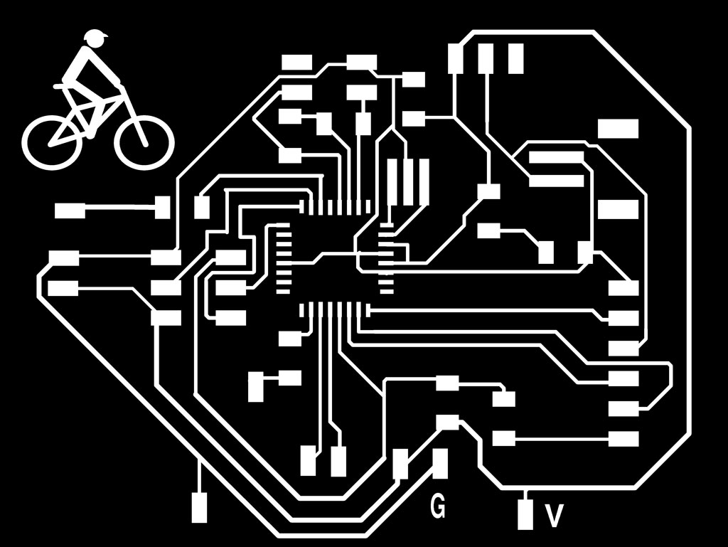
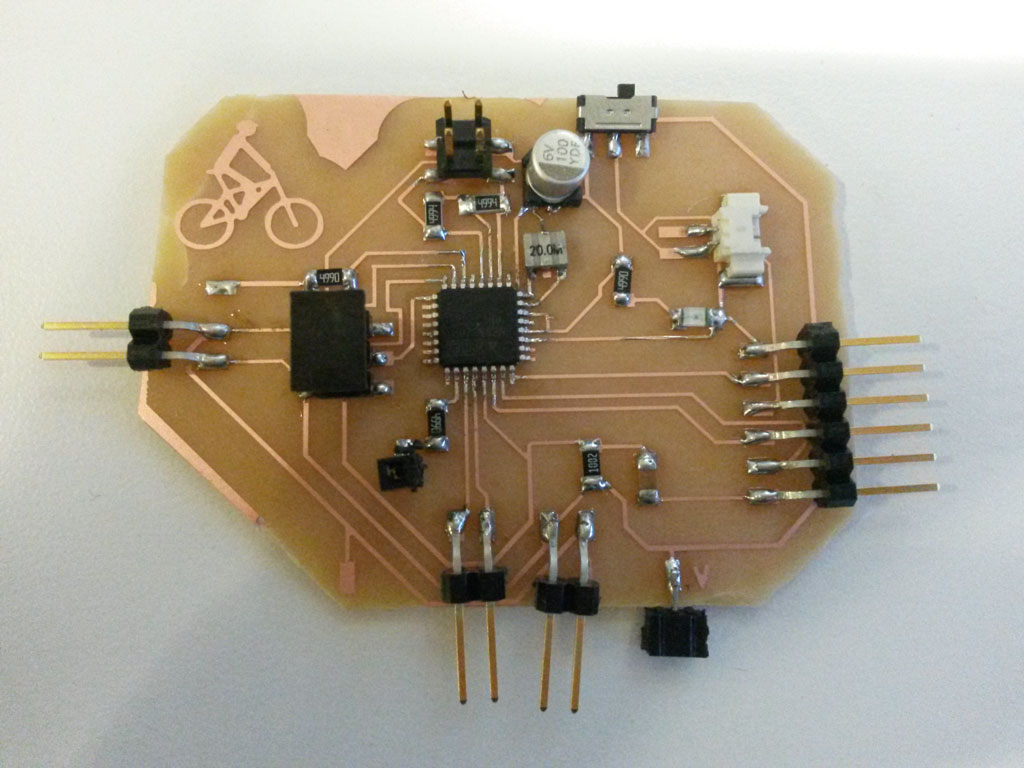
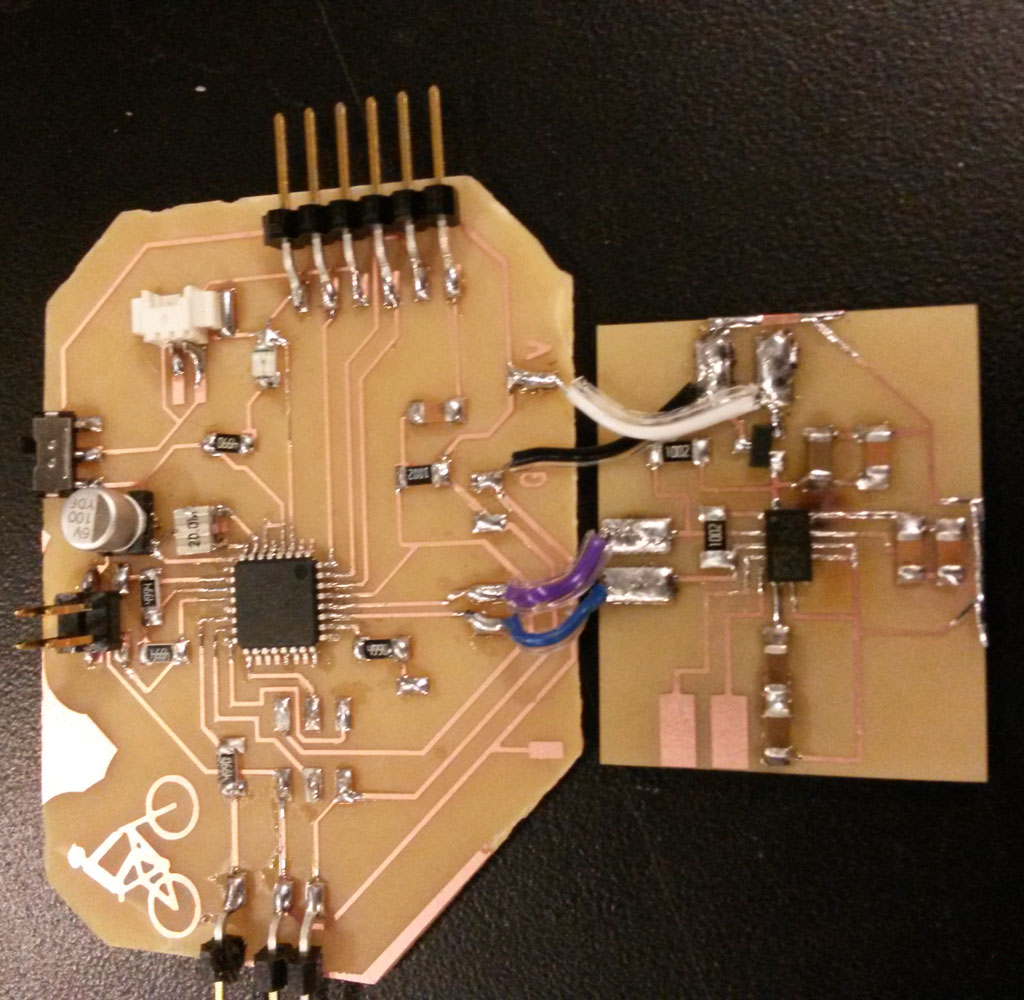
I designed the main control board. I knew I would have to use a few Arduino libraries that will probably take a lot of space, so the ATtiny84 with 8 Kbytes flash memory will not be enough. After some research about different ATMega controllers and ATXMege, I decided to use the ATMeag328P, which was in the inventory, and is also used in Neil’s hello.arduino.328P board that I could use as a reference for designing my board.
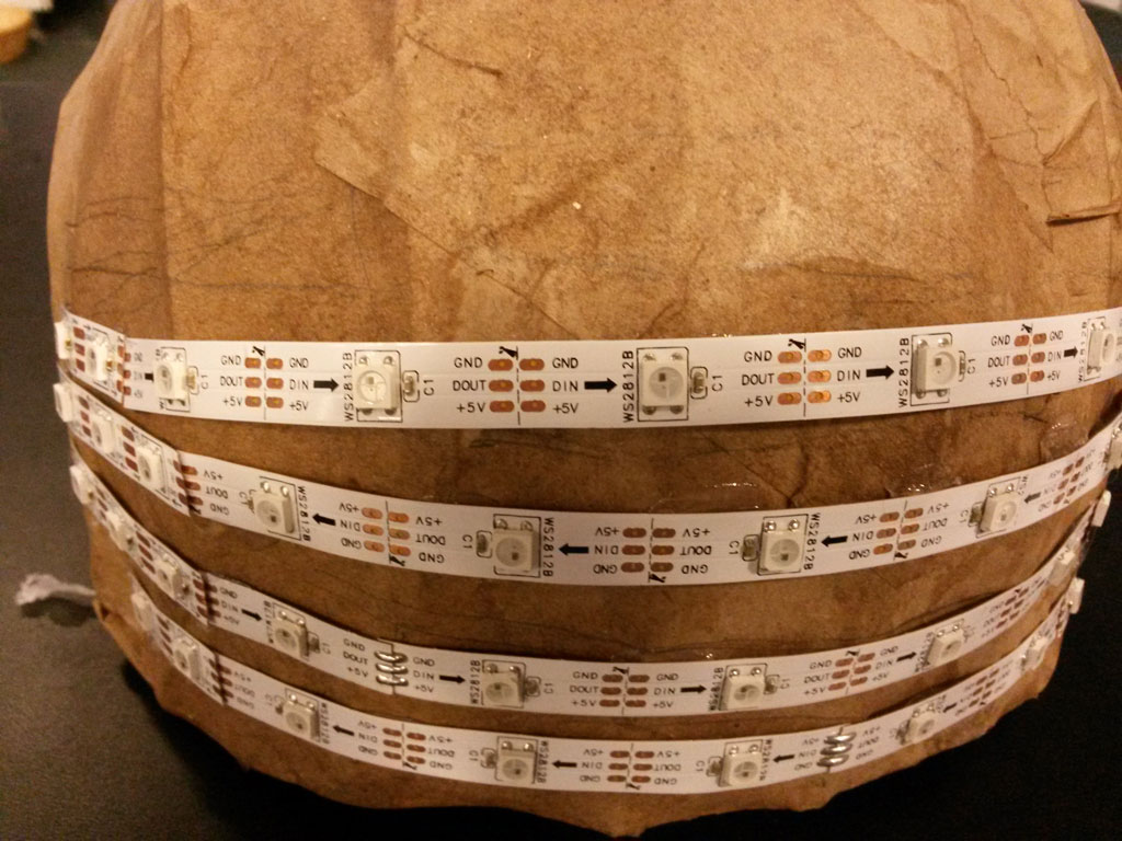
As output LEDs I used Adafruit NeoPixel Digital RGB LED Strip which is a strip of RGB LED that are separately addressable controlled by only one digital output pin. Adafruit website recommends using a large capacitor between VCC and GND for the LEDs, I used the largest SMD capacitor I could find which was 220 uF.
I added connections to SDA and SCL so I could speak to the accelerometer and also used 3 digital pins for 2 capacitive touch surfaces, that will control the turning lights. (one pin for send and 2 pins for receive.) I used 5M resistors between the send and receive pins. I added a lithium battery connector and an ON/OFF slider switch.
Programing
I then burned the bootloader using the AVR MK2 programmer and by adding this text to “boards.txt” in the Arduino library. the file is missing some lines I needed to add, I copied these line from the Arduino uno settings in “board.txt”
hello.bootloader.tool=avrdude
hello.upload.tool=avrdude
To get to “boards.txt” in mac OS: right click on the Arduino application icon and then choose “show package contents” then “boards.txt” is in Contents/Java/hardware/arduino/avr.
Then, I tested each of the components with the board separately. I used Adafruit NeoPixel library for the LED control, Adafruit LSM303 Library for the accelerometer and CapacitiveSensor library for the capacitive touch.

The entire code I wrote is based on an example from Adafruit website, that I changed to fit my needs. Since I did not want to call the delay() function in my code, I’m using many conditions, which make the code a little bit complicated to read and follow. If I would do this again I would write the whole thing as a state machine. The code I used can be found here
Assembling
After I had all the separate pieces of the helmet, it was time to assemble everything together for the final project.
I covered my helmet with paper mache, as described before, for having a surface that is easier to work on.
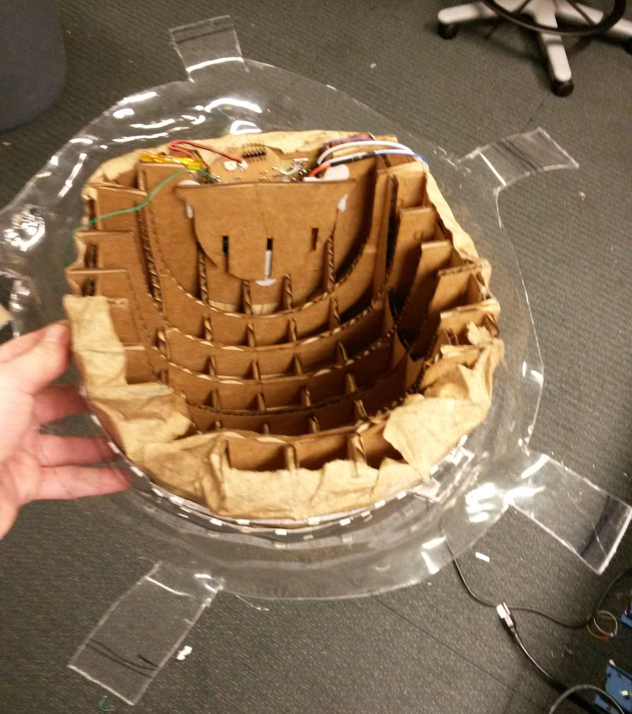
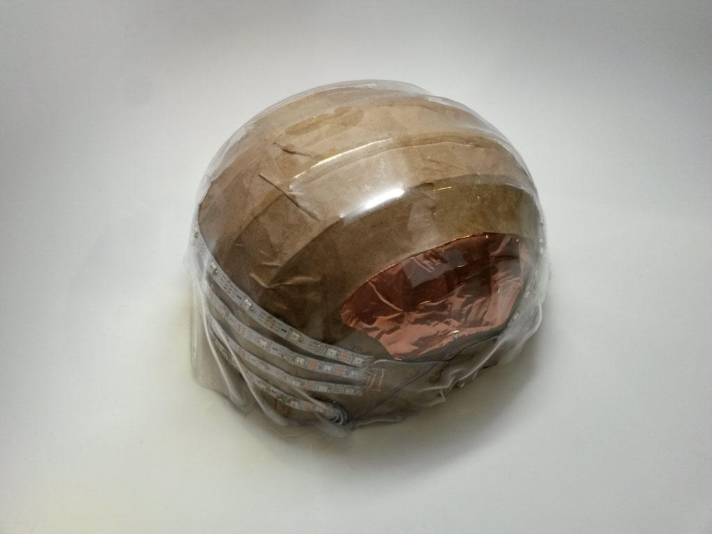
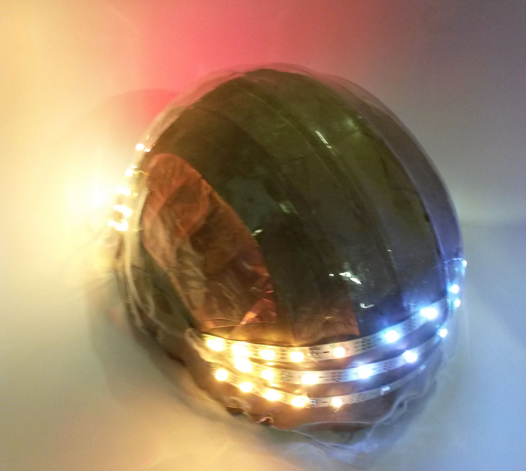
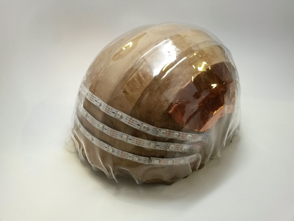
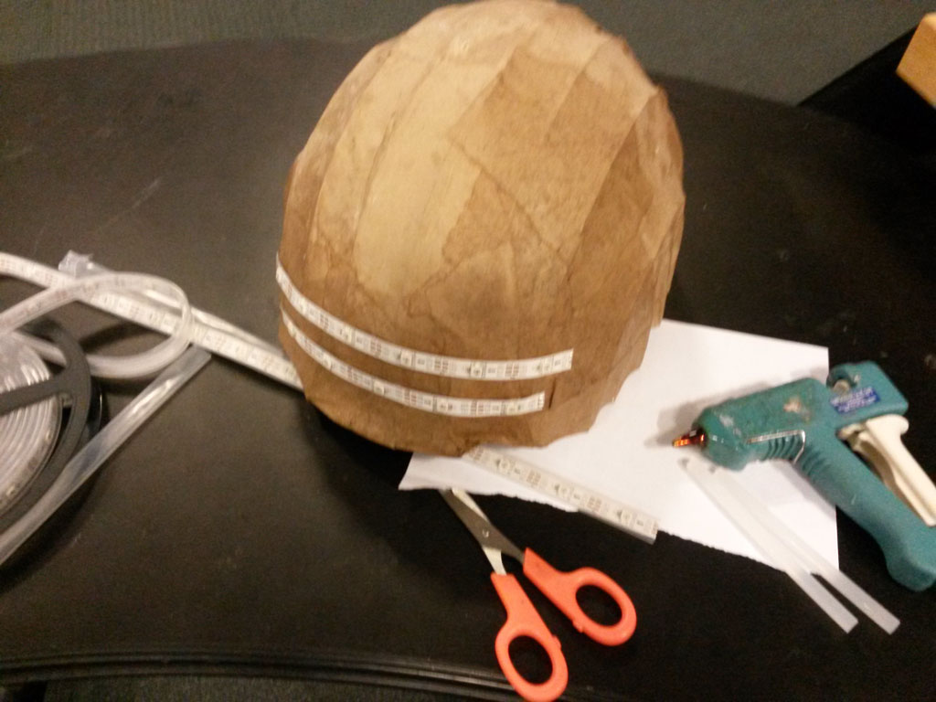
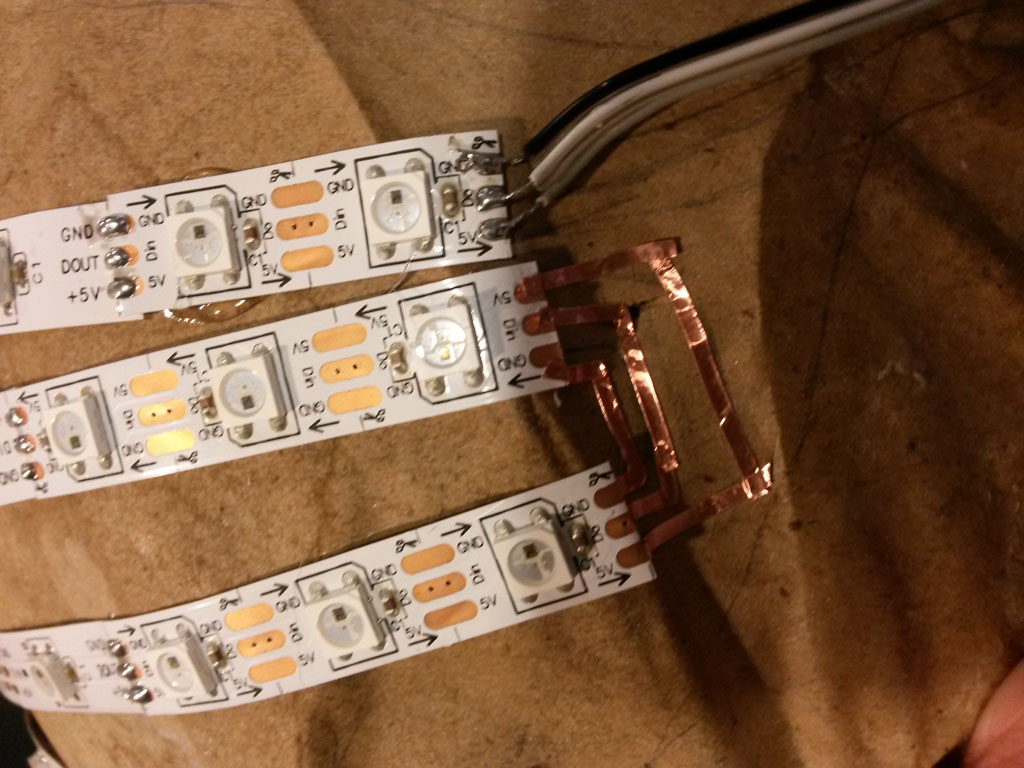
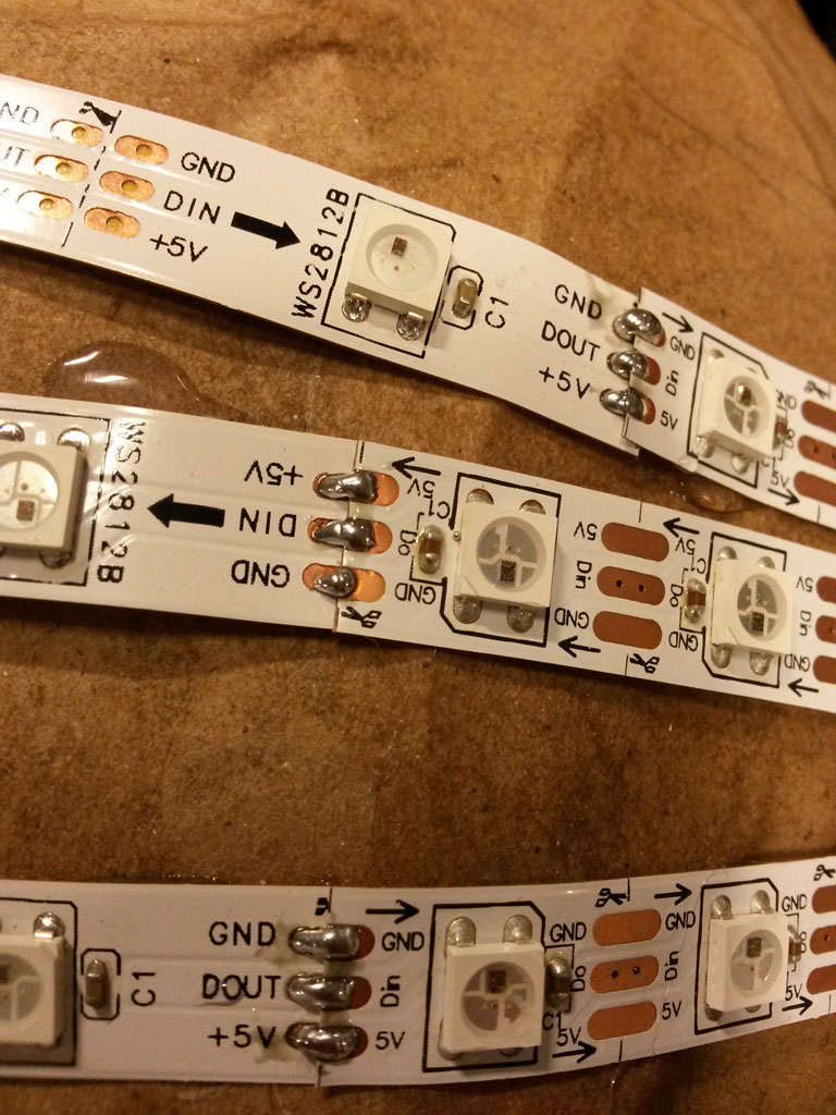
I started with fixing the LED strip on the helmet. This requires a little bit of planning ahead since the whole strip is treated as one array, and it has a direction. I draw the lines I wanted with pencil on the helmet, and then cut parts from the LED strip and glued them on the helmet using hot glue gun.
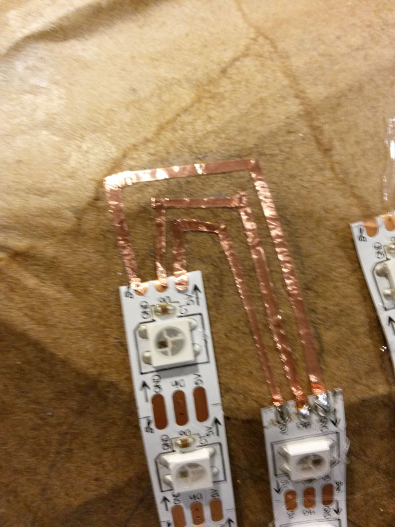
After all the LEDs were glued I had to connect them, soldering the touching points that wasn’t connected, connecting the back strip to the front strip using wires and using copper traces cut by the vinyl cutter and then manually adjusted to fit the helmet.
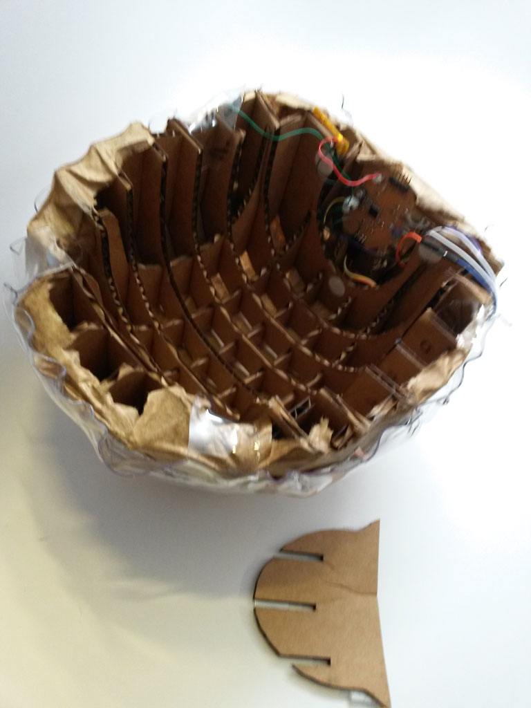
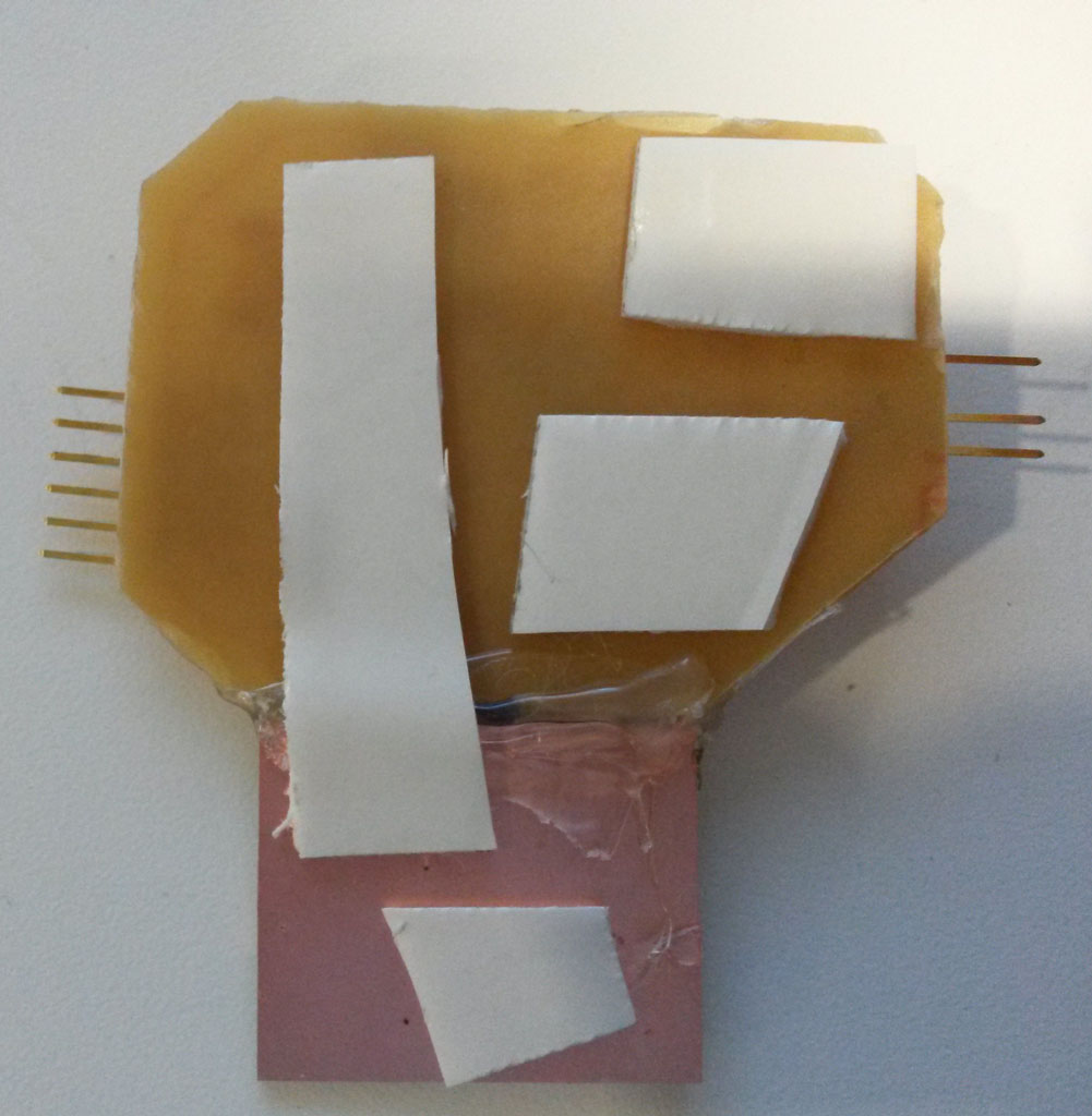
I sticked copper stickers on both sides of the helmet and soldered them to wires connected to the capacitive touch pins. After burning the bootloader to the board, I de-soldered the ISP header, to make my board more flat. I soldered the accelerometer connections to the microcontroller board and used hot glue to hold the 2 board close together.
I used double sided tape to put the board in the gap at the back of the helmet so that the FTDI slot and On/Off switch are still accessible. I sticked the battery in a slot near the board, the connector is kept out, so I can charge the battery when needed. I used sticky back fasteners to add a piece of cardboard to protect the board (and the head).

After everything was connected and working I used a heat gun to close the plastic on the helmet so it doesn’t move, I cut flaps around the helmet, to fold them inside.