Input devices
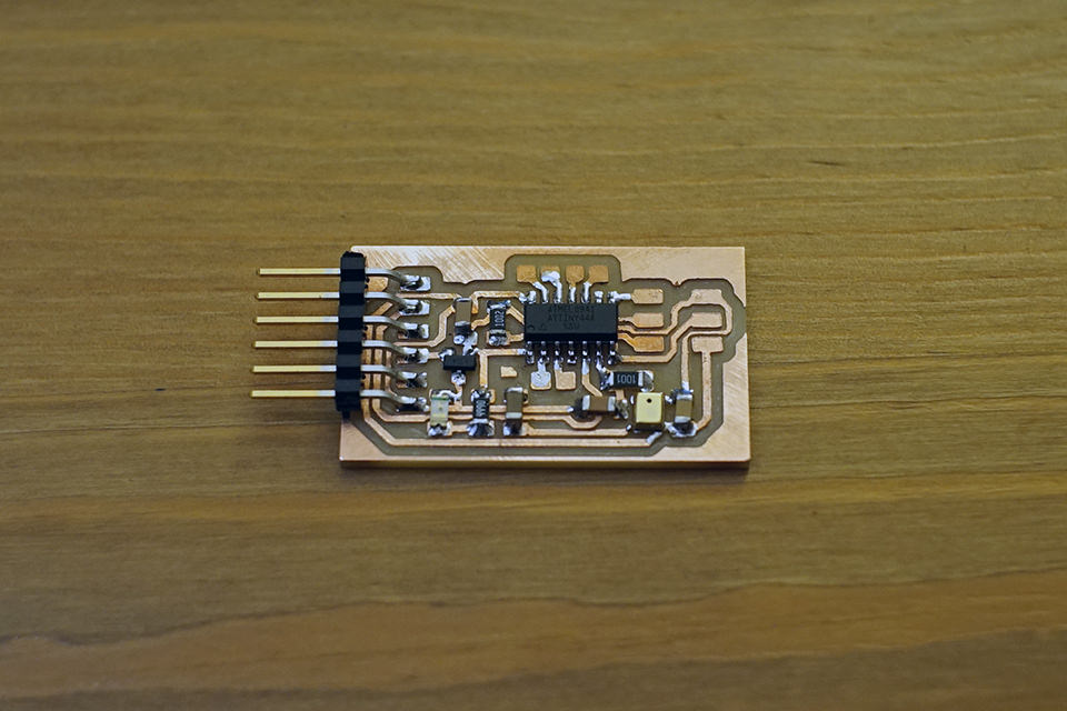
soldered board
This week I chose the MEMS example to start and learn how to make a sound collector. I focused on the software side, compared to last week, which my intention was to be confortable in milling and soldering.
sound collector
I was happy my design to milling routine take less then 3 hours by now, and make a programmable board in the first try. Fig1 shows the circuit, adding a one led to indicate light. I feel this extremely useful when hardware debugging the board. Neil's example was based on attiny45 so I changed the pin allocation for the output of the MEMS. The port was decided by the board layout to make it easy to use the open pins.
By now I think I know the right settings for EAGLE's minimum trace pitch. small footprint!!
For soldering, I used the heat hun technique to fix the MEMS part. After I checked using the multimeter, I pluged to my FTDI cable which I bought from sparkfun.
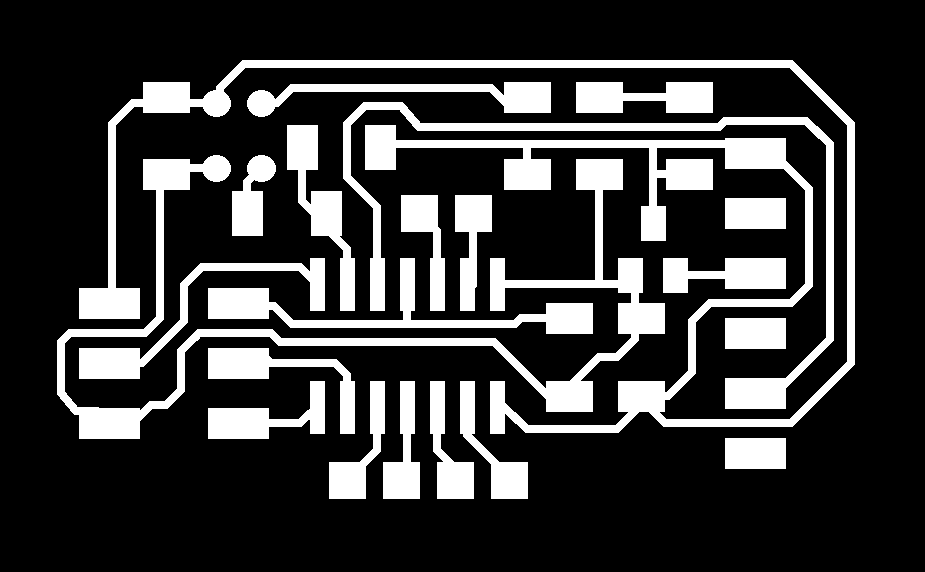
traces , board outline ,EAGLE Circuit Board ,EAGLE Schematic,

Fig1 circuity

Fig2 board trace
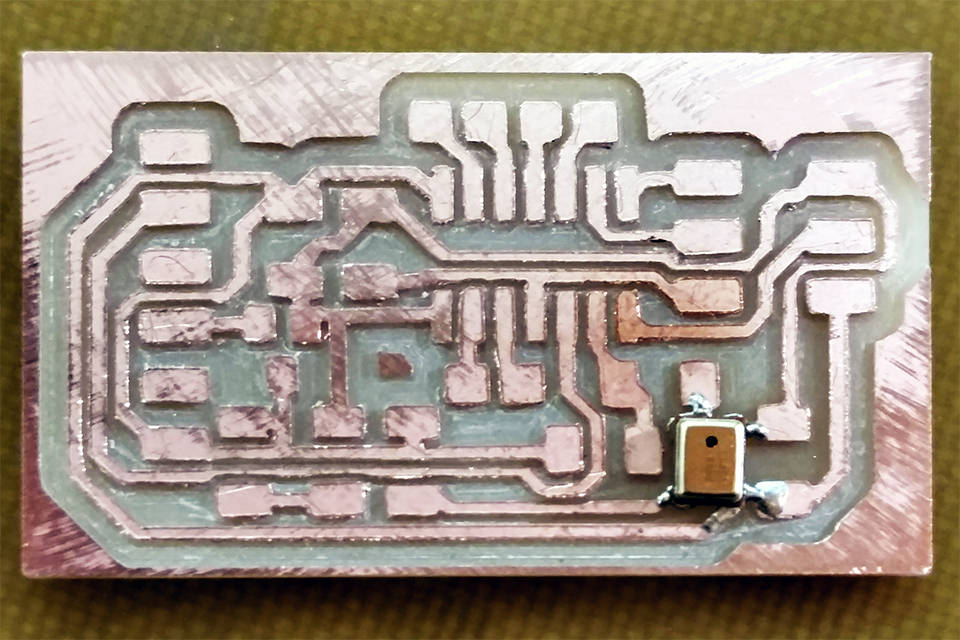
Fig3 milled well!

Fig4 with ftdi
programming
For the software side, I found it confusing about registering the MUX value. In the datasheet they seem to have 5 elements MUX[5:0], but the program only recognized 3(which is enought to disinguish 7 ADC pins), but it was reviewed on class and showed that I did not change the make file. on line MMCU=attiny44
ADMUX = (1 << REFS1) | (0 << REFS0) | (0 << MUX3) | (1 << MUX2) | (1 << MUX1) | (1 << MUX0);
I tried out to serial communicate using node.js and simple html, I had to configure the value in order to work well.
var max_value = (Math.max.apply(null,hi_nums)*256+Math.max.apply(null,low_nums)) var min_value = (Math.min.apply(null,hi_nums)*256+Math.min.apply(null,low_nums)) var difference = max_value - min_value
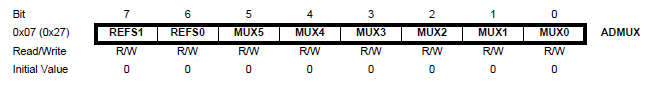
Fig4 mux trap
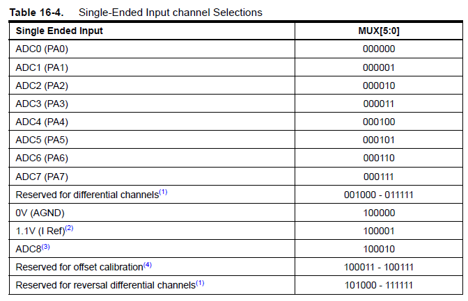
Fig5 mux trap

Fig6 overall