An exciting start to the week! The assignment was to program a custom-fabricated PCB to do something in different environments and languages. I had to start this assignment right from the board fabrication since I hadn't been able to mill the board earlier during Week 5. So, the process for me was be to i) design a schematic in eagle, ii) mill the export traces on Modela 2 via fabmodules, iii) layout and stuff the board with components and iv) program the board using different means.
Modela 2 during my earlier attempt in Week 5 was quite finicky due to some connection issues. I faced the same in my first attempt this time around as well with the server not responding at first with the error looking something as follows:
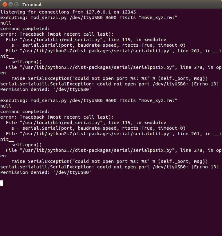 "error: Traceback (most recent call last): File "/usr/local/bin/mod_serial.py", line 115, in s = serial.Serial(port, baudrate=speed, rtscts=True, timeout=0) File "/usr/lib/python2.7/dist-packages/serial/serialutil.py", line 261, in __init__ self.open() File "/usr/lib/python2.7/dist-packages/serial/serialposix.py", line 278, in open raise SerialException("could not open port %s: %s" % (self._port, msg)) serial.serialutil.SerialException: could not open port /dev/ttyUSB0: [Errno 13] Permission denied: '/dev/ttyUSB0'"
This was apparently fixed by a chmod command on the /dev/ttyUSB0 port and Modela started responding to fabmodules command. I was almost going to resintall fabmodules as recommended by Akito, which thankfully I didn't before trying out this chmod terminal command.
The fabmodules have changed a bit since the last time (electronics design assignment)
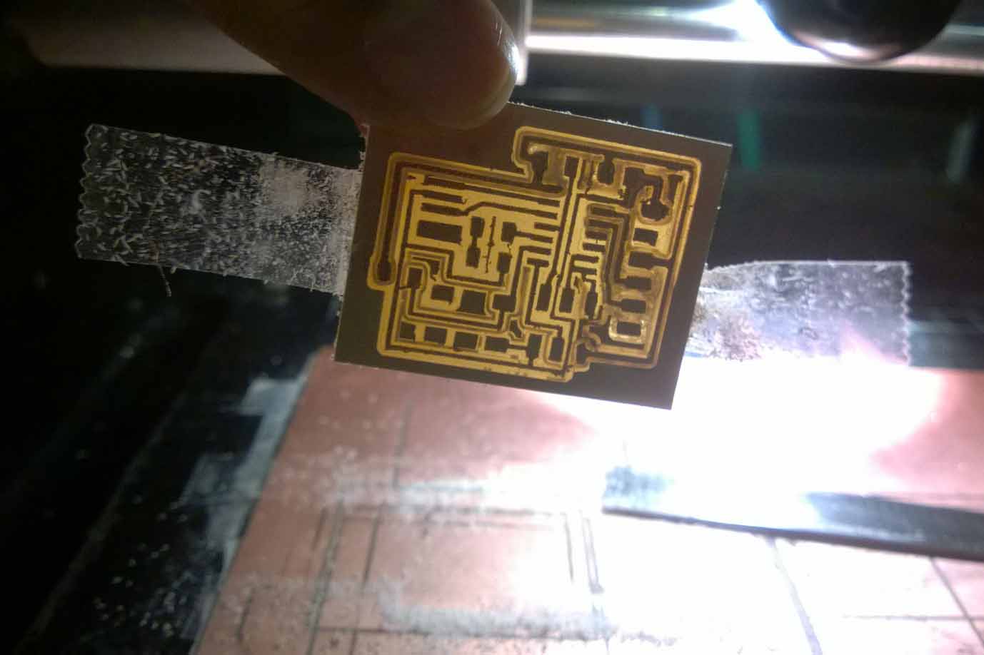
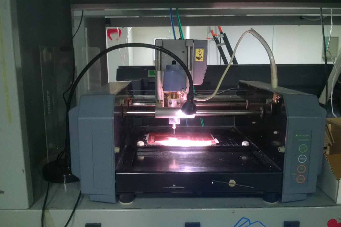 and they now carry an option to select the milling machine from the fabmodules (such as MDX 20, MDX 40) etc. It was Roland (.rml) MDX 20 in our case and the default settings show up once you select your traces, 1/64 milling size and the milling machine model. I went ahead and milled the boards with the default settings and the endmill seemed to be cutting a bit rough, even as I used razor to scrape the board after milling.
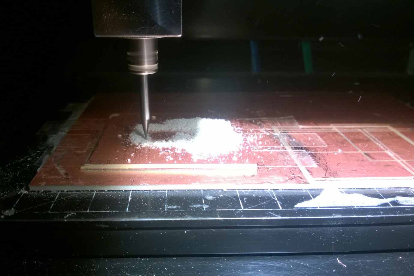 I later found that if you play with speed (set it to 2 instead of default 4) and offset overlap (as 50% e.g. instead of default), you get a much nicer output of the milling. However, it wasn't much of a concern even if it was a bit rough (scrape it with a razor nicely after milling) and I tried milling multiple variations with offset 4, 5 and 7 with the last options giving the finest result.
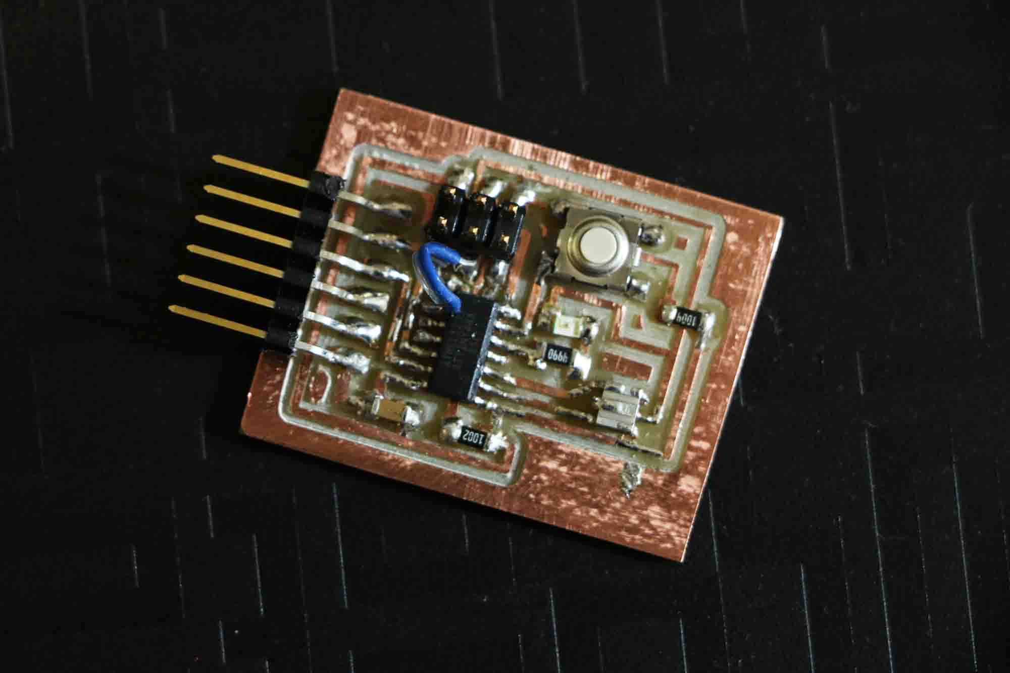
 I'd been underestimating myself about my soldering skills and the board stuffing was a breeze. Time to actually program the board!
I was working with AVR ISP programmer to program the board. The header of the AVR ISP goes to the ISP header and the FTDI header needs to receive
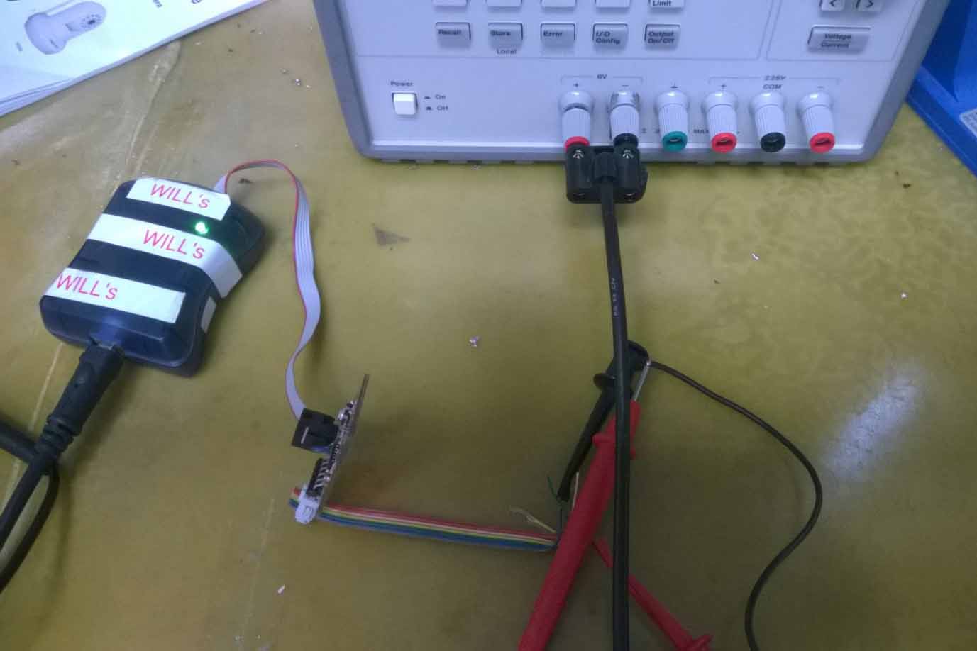 power on VCC as well GND connection. I didn't have a power supply cable and the lab seemed to have only one available, so Amanda showed me a hack to connect the ribbon cable with the crimp and use two of these wires with VCC and GND from a big power supply unit in the lab (5.0V is actual voltage required for the boards on FTDI).
If you're on Mac, download Crosspack and downlod FTDI Virtual COM Port drivers before you can begin doing anything with AVR programmer. Run the commands that Neil mentions on the website.
1. make -f
However, the short was not visible and the solder was all flowing outwards rather than inwards to short legs from under the parts. Amanda looked at the schematic and suggested about possible short during milling process due to less spacing than required. We uploaded the traces on fabmodules and saw that there was an evident short due to two traces getting joined together.
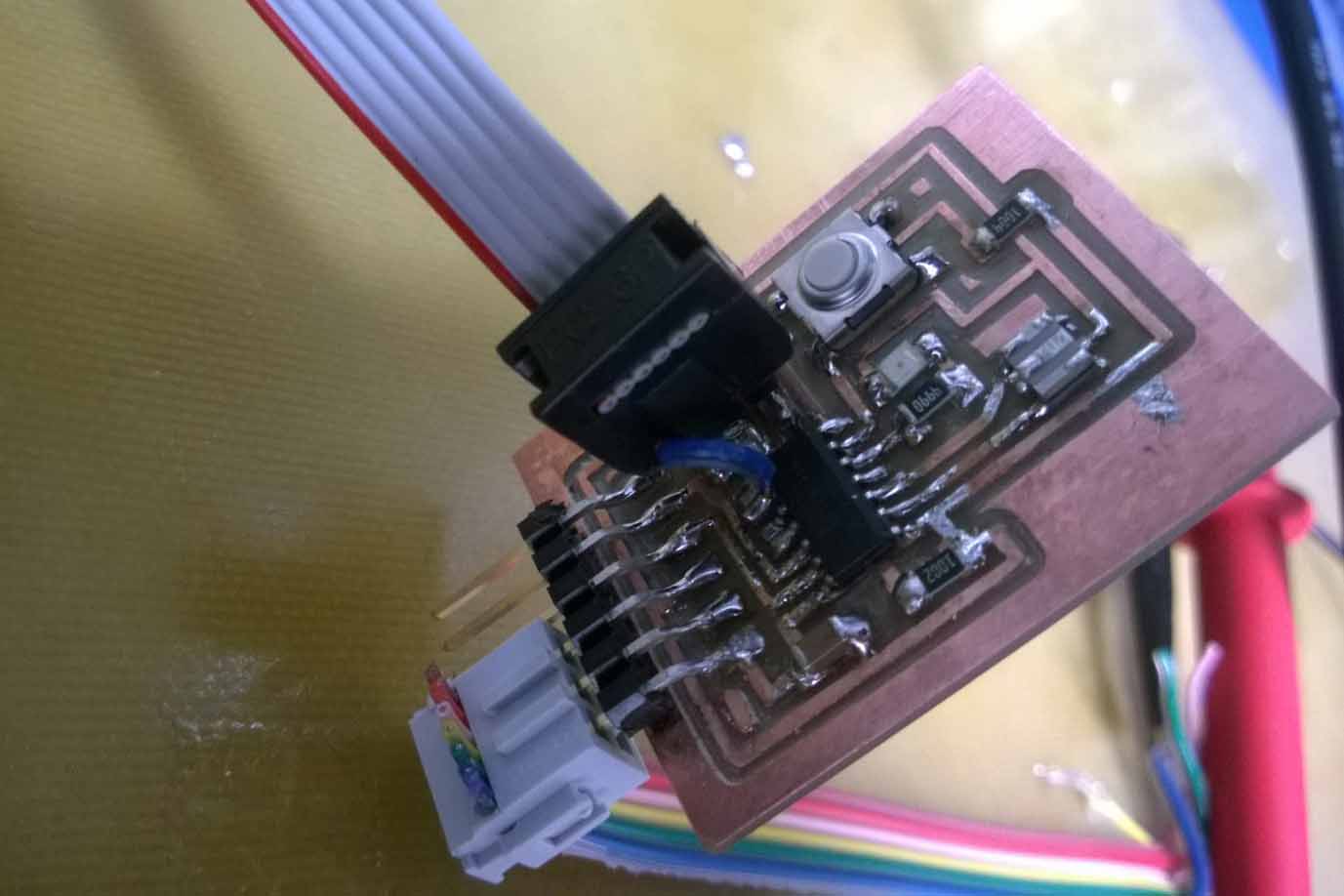 Another hack! I chipped out the trace from SCK leg of header and stopped the short from happening. I put a wire jumper from this leg to the PA4 of ATTINY and checked continuity again. The short was removed and the connections seemed to work as they should have been with the right traces. With the avrispmkii fuses working, I verified that the boards was now ready to receive programs.
If you're using Arduino IDE to program the board, follow the HighLow Tech instructions about i)adding Additional Boards Manager URL in the Arduino Preferences, ii) Tools > Boards Manager > Install ATTiny, iii) Processor as ATTiny44, iv) Clock as 20Mhz. iv) Select the right Port, v) Burn the bootloader.
On trying to select the Port in my case, we found that the ribbon crimp hack to use the big power supply from the lab didn't work becasue the other data pins were somehow also getting used somehow in the process. So, I resorted to using the FTDI power cable after all.
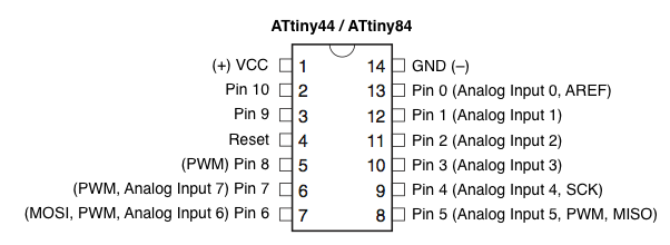
Write in your programs and upload as you do with Arduino normally and see it all in action. Remember that pin addresses are a bit different in ATTINY and look as in this schematic.
More and more programming languages and programs to follow soon.