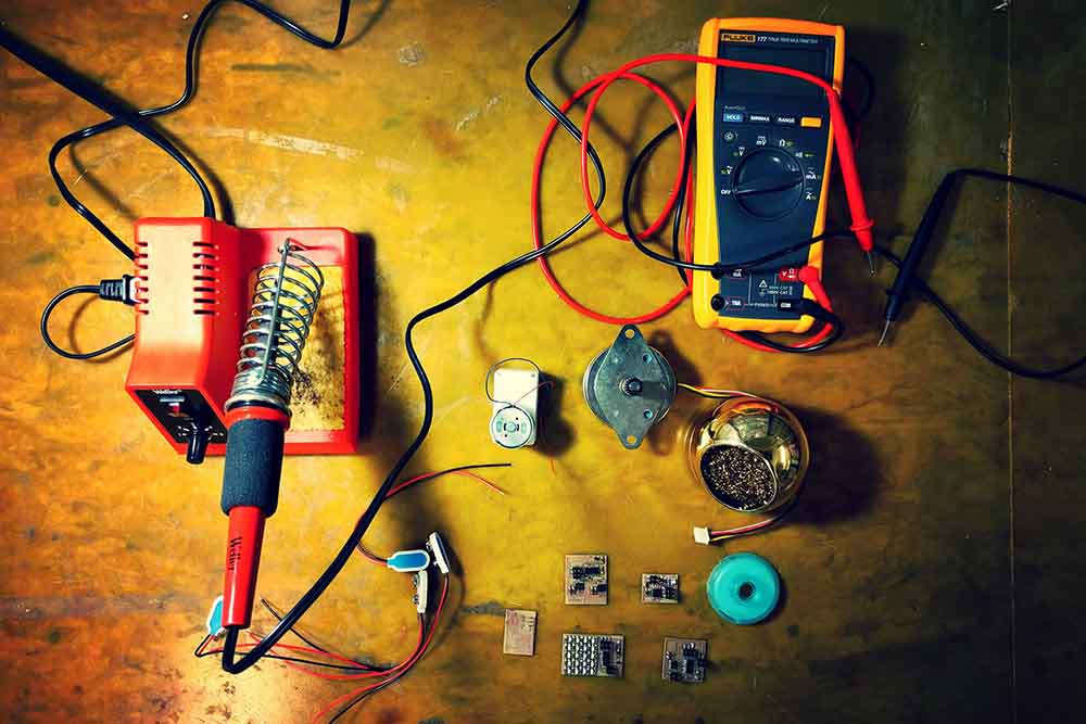
 Output devices week is about driving things such as LEDs, motors (stepper, dc, servo), speakers, LCDs etc. through PCBs fabricated from scratch. I intended to make a Drawing Robot that is gravity suspended and driven to points via two opposite steppers pulling/releasing as per drawing pattern. However, it seemed to be quite a jump from the previous hello world program of embedded programming. So, I decided to start with the output devices I would likely be using in my final project to understand their driving mechanism and embedded programming. I made the boards for RGB LED, LED Array, DC Motor, Servo Motor and Stepper Motor.
I milled the boards on Modela 2 for the gazillionth time. All of the boards seemed to come out fine, except two. Some of the traces for the
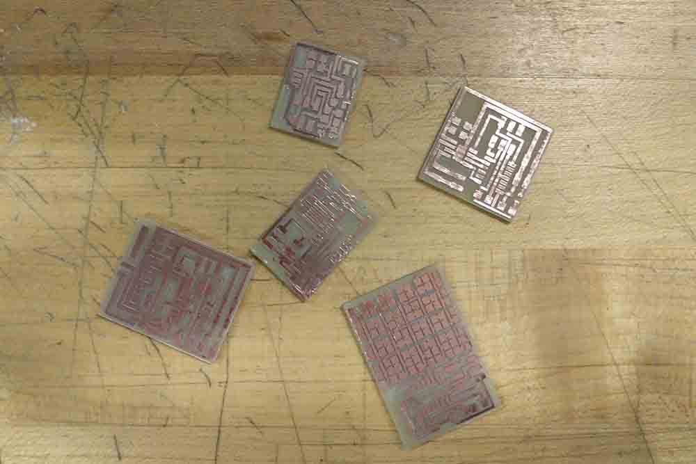
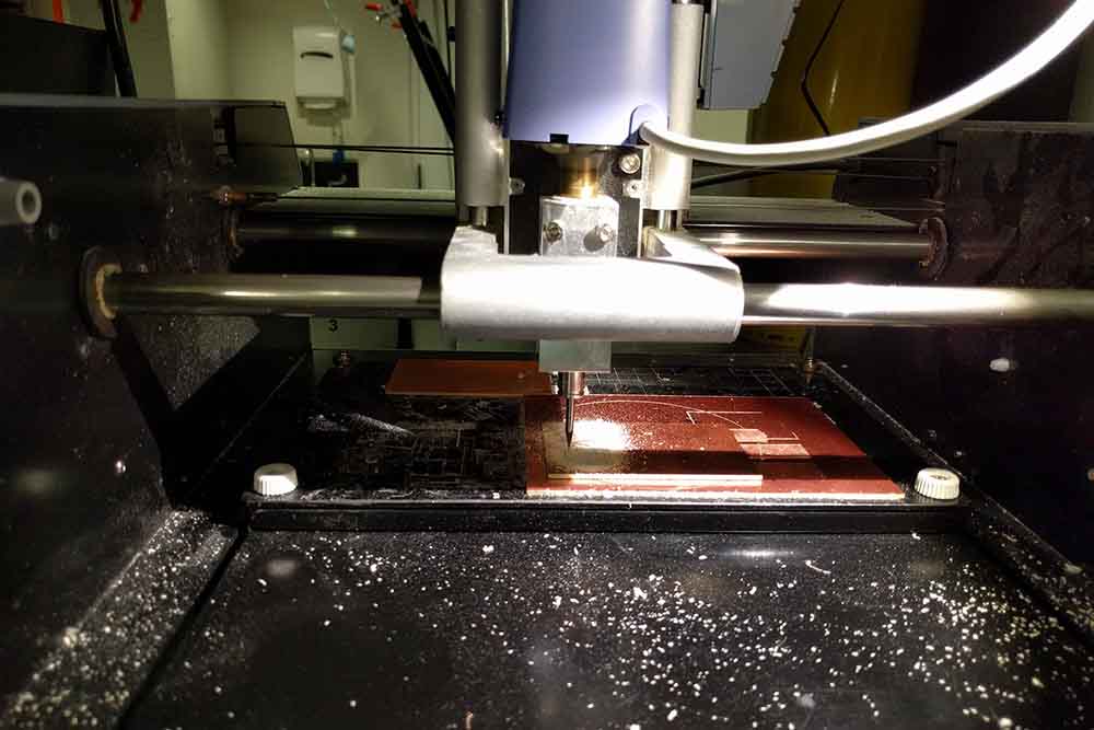 stepper motor seemed to be too close and fabmodules interpreted them as one in the toolpath calculation, which turned out to be a short in the end. This happened at two places in the board and I used an exacto knife to the manually create a separation for the paths.
The milling for the servo all turned out to be fine, except some finicky issue with Modela towards the end of the process when it didn't cut traces for a certain part at all resulting in shorts. This seemed to be a bit cumbersome to solve, so I decided to keep it for the next time.
stepper motor seemed to be too close and fabmodules interpreted them as one in the toolpath calculation, which turned out to be a short in the end. This happened at two places in the board and I used an exacto knife to the manually create a separation for the paths.
The milling for the servo all turned out to be fine, except some finicky issue with Modela towards the end of the process when it didn't cut traces for a certain part at all resulting in shorts. This seemed to be a bit cumbersome to solve, so I decided to keep it for the next time.
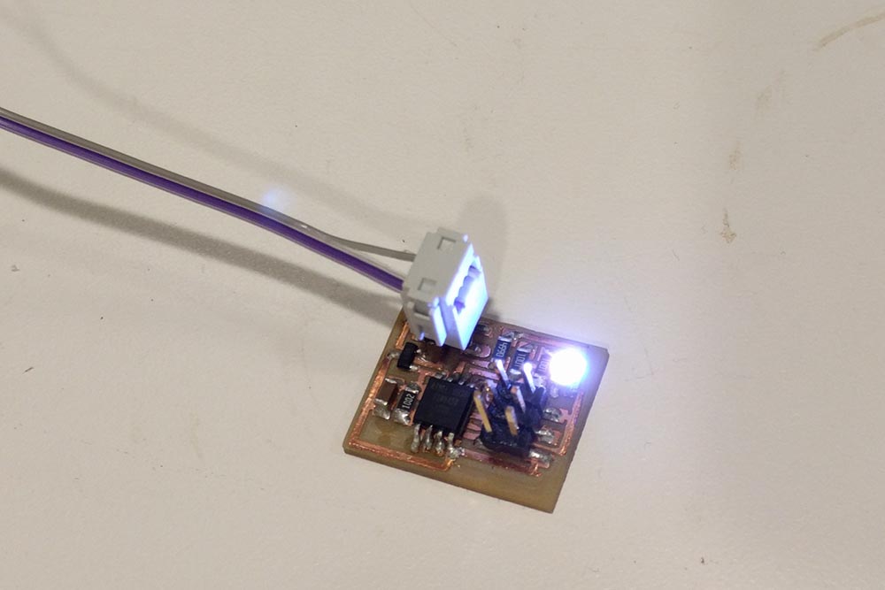
This process was followed by soldering. RGB LED board has a ATTiny 35 whereas the other boards had ATTiny44.
 I hadn't previously been able to
program the board in C (Neil's code) with AVR, and had earlier executed code through Arduino. I assumed that the issue was with not using FabISP
for programming the boards. So, I got my FabISP and it didn't seem to get detected on the computer USB anymore. The multimeter debugging didn't seem to show any anomalies and after spending a long time, I decided to mill another FabISP itself.
I hadn't previously been able to
program the board in C (Neil's code) with AVR, and had earlier executed code through Arduino. I assumed that the issue was with not using FabISP
for programming the boards. So, I got my FabISP and it didn't seem to get detected on the computer USB anymore. The multimeter debugging didn't seem to show any anomalies and after spending a long time, I decided to mill another FabISP itself.
 The new FabISP somehow was showing rc=-1 errors during programming of the FabISP. Even after checking for shorts, pin misplacements/mismatches, there seemed to be no apparent reason coming out. Another long session od debugging later, I decided to mill another FabISP and program it to make it a programmer, but it turned out to be a way easier option to go back to AVR ISP programmer.
 I downloaded the make files for the programming the RGB LED board to begin with and was confronted with an error that was solved by just checking for the shorts and removing a small shaving that was creating this (although I had soap-washed the board and scrape cleaned it with a razor). The commands go as follows:
i. make -f sample.c.make
This creates a hex file
ii. sudo make -f sample.c.make program-usbtiny-fuses
If you look at Neil's makefile, it suggests that if you're using AVR ISP instead of FAB ISP, then you need to change this command as sudo make -f sample.c.mame program-isp2, which is what I had to do. This process is essentially similar to 'Burn Bootloader' option that you'd have to Arduino IDE, if you were programming the board usign Arduino IDE.
iii. sudo make -f sample.c.make program-usbtiny
This progress then transfer the program to the board now and starts executing the instructions.
I verified the working of my RGB LED program
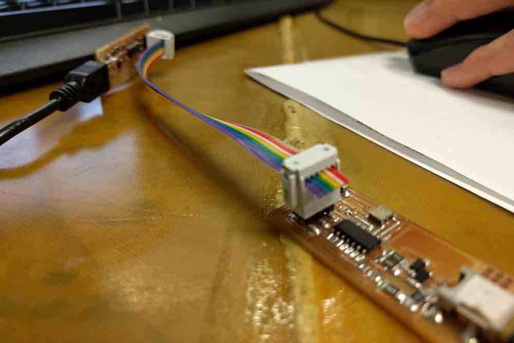
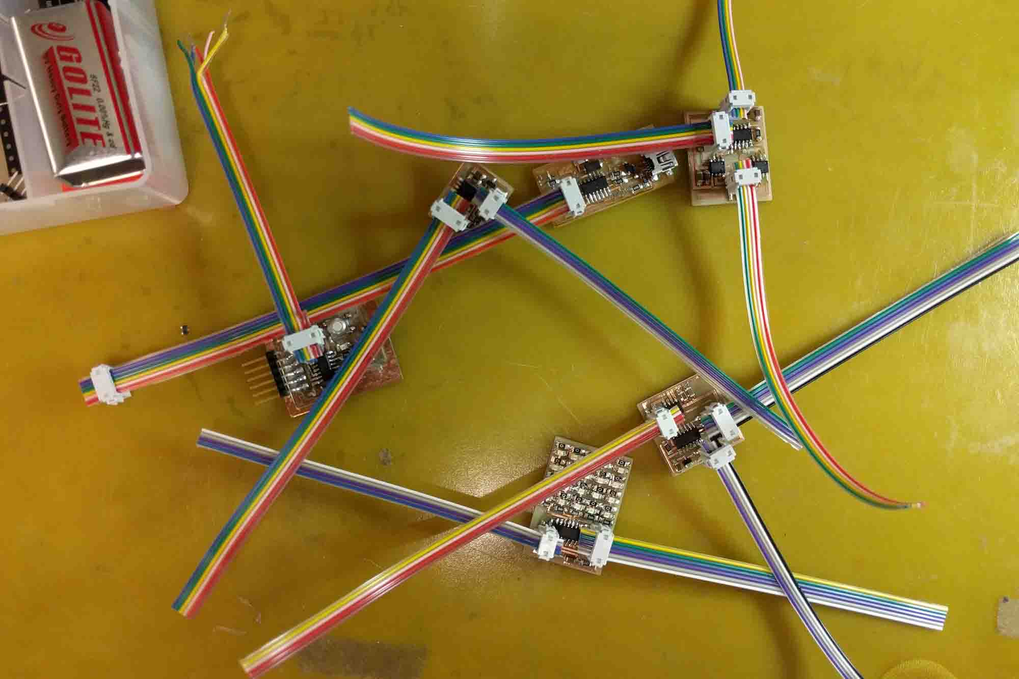
Following this, I went on soldering the other boards. The LED array with 25 LEDs and a lot of soldering was the only one which seemed to be a bit trying. After the first soldering attempt itself, all the baords turned out to be connected perfectly without any shorts or misconnections as tested by the multimeter.
The same steps for programming the boards followed with AVR programmer. LEDs, Motors, Speakers and other output devices do need external power for
 driving, which can come from an external desktop power supply, battery etc. The regulators on the boards ensure that the voltage gets reduced to 3.3V or 5V depending on the board, but care needs to be taken about the voltage being given to the regulator and to not overshoot their ratings.
Also, the boards have power input headers and the supply leads should be connected in the right polarity, the same applying for the output device such as motor being used.
driving, which can come from an external desktop power supply, battery etc. The regulators on the boards ensure that the voltage gets reduced to 3.3V or 5V depending on the board, but care needs to be taken about the voltage being given to the regulator and to not overshoot their ratings.
Also, the boards have power input headers and the supply leads should be connected in the right polarity, the same applying for the output device such as motor being used.
All the boards seemed to be running after the programming for which the videos as below.
Assignment: After all these available examples, I went to design one of my own boards and wanted to use an ATMEL 88A/328p chip this time. This is the chip that is used in Arduino and while I wasn't planning to use all the pins on this chip for this assignment, I thought of this as a good exercise for the upcoming project of input devices where I intend to use SPI communication with an external peripheral device.
I designed the board in Eagle with ATMEGA 88A THIN smd package (88A is the package from same family of uCs i.e. ATmega48PA/88PA/168PA/328P). I was planning to break out all the pins except for an LED (which is actually not the best thing if you're upgrading to a better uC since you'd doing that to get more pins, ram, rom in the first place). The things to take care of are pull-up resistor required at RESET pin, connections of the ISP header pins to appropriate pins on 328p. Further steps after designing the schematic are: i. Route the baord and export traces, ii. Mill the board, iii. Stuff the board with the required components (no biggies here except the change of the uC chip)
I was using an AVR programmer to program the board, but realized that I have a malfunctioning programmmer after multiple levels of debugging. However, the process to program the the 328p with the AVR needs either
1. keeping the appropriate boards.txt file in the Documents/Arduino/hardware/xyzDuino/boards.txt, or
2 .pasting this link in the Arduino IDEs preferences.
The new AVR programmer that I was able to get my hands on was able to successfully burn the Bootloader. I was using an external clock (20 Mhz Resonator) in my board (8 Mhz is the internal clock), so burning the bootloader requires selection of the right
1. Board (should appear after you paste the link or boards.txt in the right place),
2 .Processor Version (328p in my case),
3. Processor Speed (20 Mhz in my case) and
4. USB Port
After successfully burning the bootloader, the pinout of 328p showed that my LED pin was on D2 (digital pin 2, I broke out all the Analog pins). I had an additional LED on SCK pin of 328p which is PIN 13. I tried to upload a sketch that blinks these LEDs together and it failed. A few minutes of debuggin later, I realized that there was a problem in my schematic, in that the RESET pin from the FTDI wasn't going anywhere, so I decided to use the AVR programmer for program upload instead. To do that, you just have to Tools > USe Bootloader > Select No (ISP Programmer Upload). This got me up and running with this simple sketch and to check if everything was fine with my board. In terms of programming this C, I wrote this short and simple program.
The process of uploading the program to the board now involves:
1. Make the hex file
2. Upload the fuses like burning the bootloader in Arudino (if you haven't done this earlier using Arduino IDE)
3. Upload the program
This got me runnig with C as well to this output device using ATMega 328p chip. (Code as follows:)
#include avr/io.h
#include util/delay.h
#define DELAY_MS 1000
int main(void){
//Set 2nd bit of data direction register as 1
DDRD |= _BV(DDD2);
while(1){
//Port is used as output. PIN is used as input to read values from outside
//OR the second bit of Port D i.e. Pin D2 in our case with the already existing bits in Port D
//_BV means Bit Value and the macro actually convert this to 1 << PORTD2
//which translates to pin that you want to turn on
//E.g: 1 << 2 would translate to 00000100 and _BV as a macro inlining bit shifting operations does exactly that
PORTD |= _BV(PORTD2);
_delay_ms(BLINK_DELAY_MS);
//~_BV would give you inverse of above i.e. all the bits except as 1 the Port D2
//11111011 -- this will turn off the Port D bit
PORTD &= ~_BV(PORTD2);
_delay_ms(BLINK_DELAY_MS);
}
return 1;
}
Bonus!
I 3D printed a plethora of parts for the DrawBot. Instead of making it run with an Arduino, I intend to make my own driver that can two stepper and one servo. Perhaps the application programming will feed into this task as well to decompose images into the points/stokes that need to be made by the suspended robot. Until next time!