 Input Devices is the week when we are supposed to measure something by adding a sensor to a microcontroller board. I also took this week to learn about the highly popular ATMEL 328p chip that goes in most Arduino boards. Unlike ATTiny44 which only had 4KB ISP flash memory, 256-Byte EEPROM, 256B SRAM, 12 general purpose I/O lines, ATMEL 328p has 32KB ISP flash memory with read-while-write capabilities, 1024B EEPROM, 2KB SRAM and 23 general purpose I/O lines. This is not to say that 328p is the next jump from ATTiny44 but there are other MCUs to look at for more pins/flash memory such ATMEL88A. I decided to use this MCU because of it's availability in the lab and its potential application in my final project.
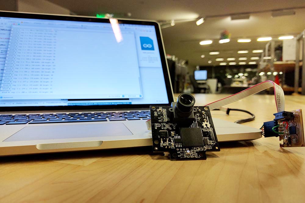
 I was very interested in interfacing a camera with my MCU board and looked at a number of options including USD 10 option Yosoo OV7670 300KP VGA Camera Module discussed by Neil in class. This camera can sample upto 30 fps and a resolution of 640 x 480. However, when it comes to cameras and MCUs, the MCUs needs lot of juice for image processing to do anything interesting unless you're tyring to do motion detection etc. in which case you might as well use a pyroelectric sensor. While googling around, I found this open source project by CMU about programmable embedded color vision sensors that can provide cool on-board real-time vision processing. The latest vision sensor CMUCam5 can learn objects of interest (through hue-based color signatures), can capture images of 1280 x 800 and can output at 50fps after processing detected objects. The camera has :
an on-board NXP LPC4330 204 MHz dual core processor,
Omnivision OV9715, 1/4", 1280x800
RAM: 264K bytes
Flash: 1M bytes
and can output through UART Serial, SPI, I2C, USB, digital and analog
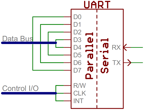 Serial Communication is by far the most common communication protocol and can support comm. with a single device device at a time. Unlike parallel comm., only two lines - Tx & Rx - are used to transfer data (more common asyncronously without clock signal but still having bits in a frame with start, stop or parity bits). While this is the most commonly used, it is often slow and has a large overhead of extra bits every byte transfer. SPI Communication uses the pins in the header i.e. MOSI, MISO, SCK, RST, VCC, GND for transfer of data and does so at a very high speed. However, the trade-off is that there can only be a master node and multiple slave nodes while possible become difficult to manage due to shear number of connections. I2C is the best of both worlds, wherein multiple Master nodes and multiple Slave nodes are possbile.
 Each I2C bus consists of two signals: SCL and SDA. SCL is the clock signal, and SDA is the data signal. The clock signal is always generated by the current bus master; some slave devices may force the clock low at times to delay the master sending more data. Messages are broken up into two types of frame: an address frame, where the master indicates the slave to which the message is being sent, and one or more data frames, which are 8-bit data messages passed from master to slave or vice versa. Data is placed on the SDA line after SCL goes low, and is sampled after the SCL line goes high. The time between clock edge and data read/write is defined by the devices on the bus and will vary from chip to chip.
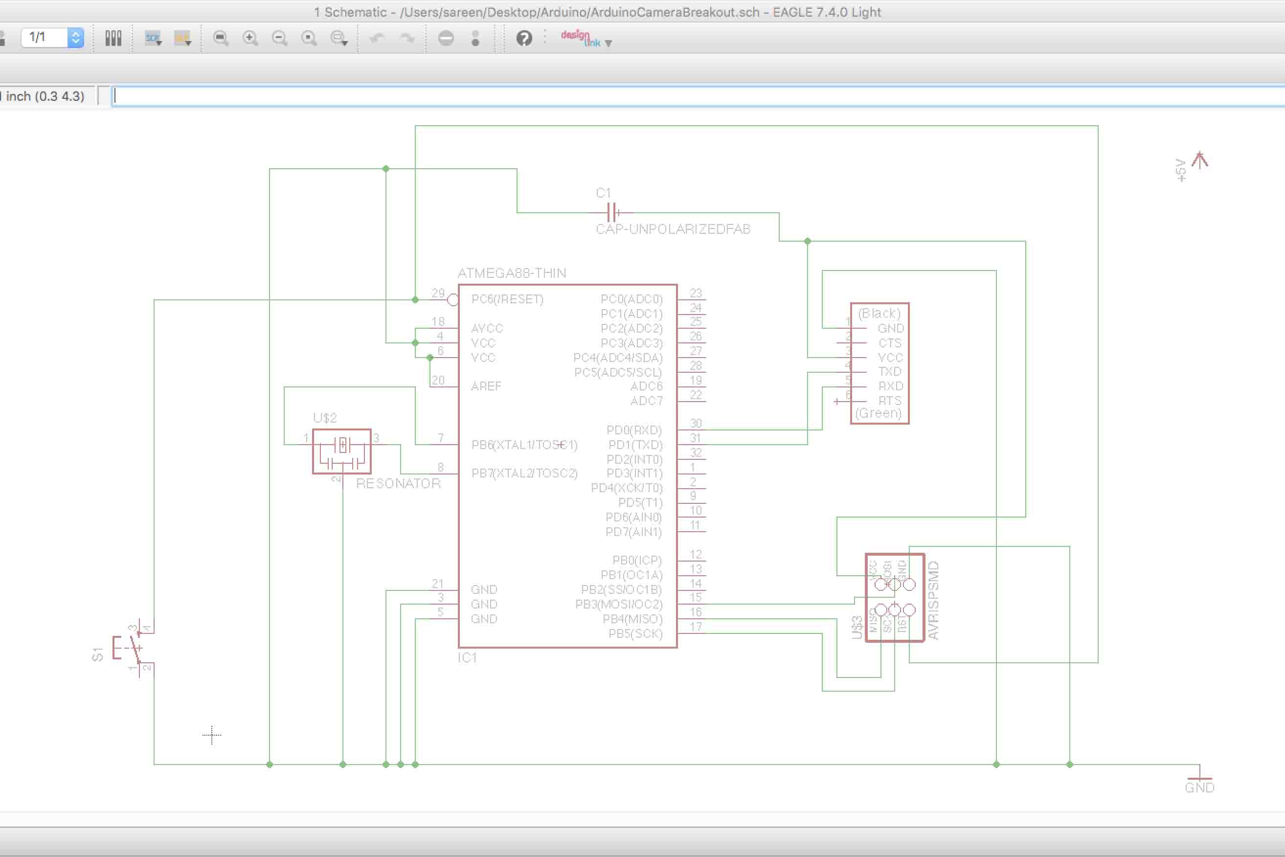
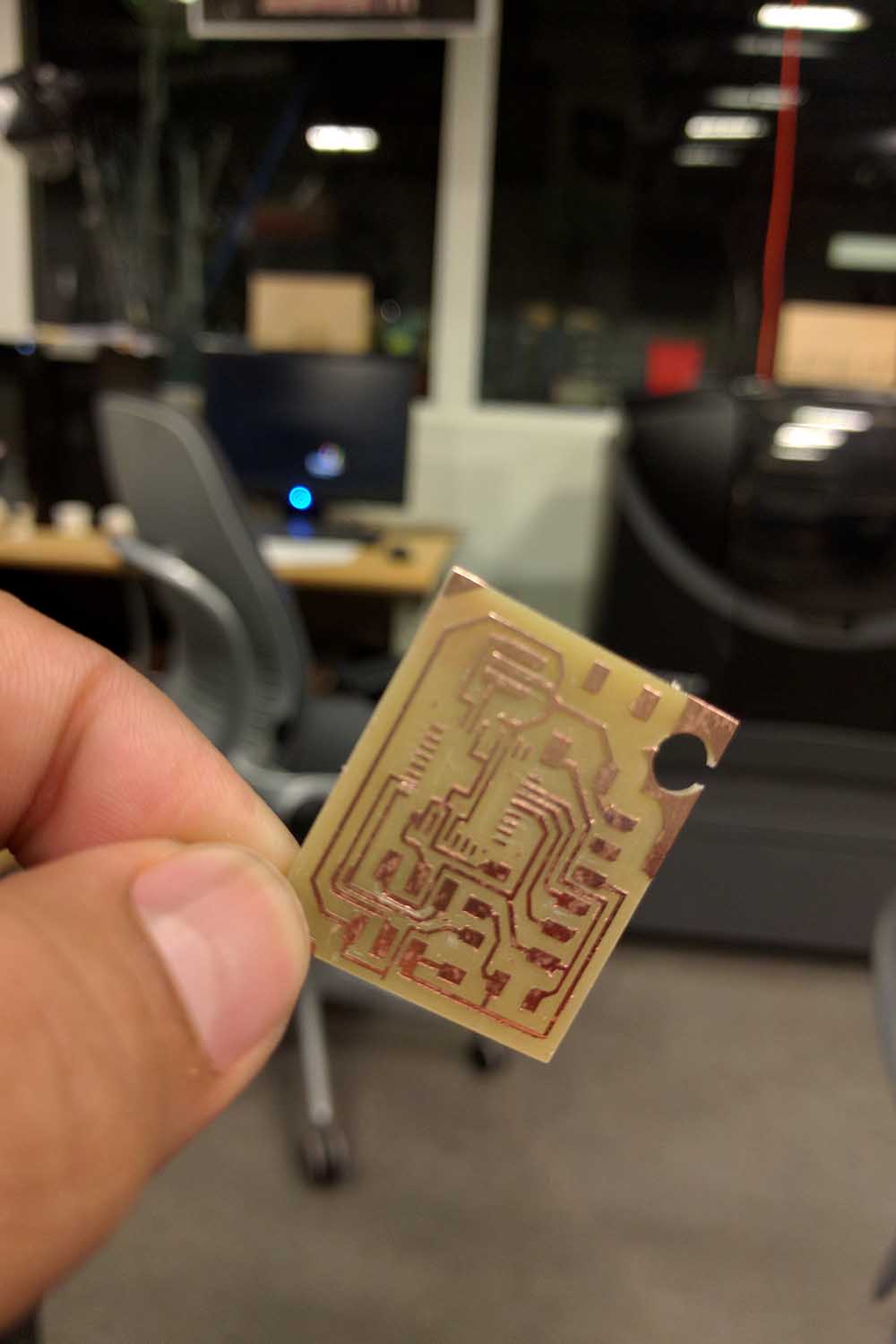
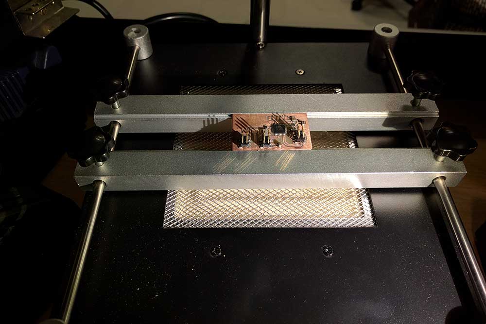 I decided to have the ATMEL 328p pins interface with this new CMU vision sensor and accordingly built a schematic in Eagle. The only two things to take care of in a circuit with this MCU when all other pins are broken out are: i. RST pin needs a pull-up resistor and ii. cap b/w Vcc and GND to smoothen noise/ripples. After having finished the schematic, the routing was simple. The process leads us to milling followed by stuffing. I used 1/64 inch endmill while trying to mill the traces for this chip and not 0.010" endmill which is only suited for very very fine and short traces. You'd need to take care of the sacrificial layer, sharpness of the endmill, no bumps with any kind of tape overlaps, snugly fitted screws etc. Here's how the quality of the output looks like:
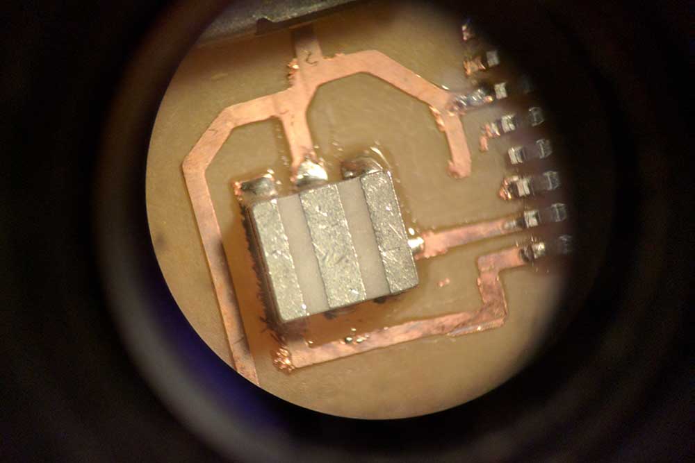 I decided to do the stuffing using solder paste and reflow oven; and not directly using the soldering iron. With the application of slight solder on the traces, all the connections seemed to turn out fine. I interfaced the camera's output with the ISP header for SPI communication and uploaded the following code:
void setup()
{
Serial.begin(9600);
Serial.print("Starting...\n");
pixy.init();
}
void loop()
{
static int i = 0;
int j;
uint16_t blocks;
char buf[32];
// grab blocks!
blocks = pixy.getBlocks();
// If there are detect blocks, print them!
if (blocks)
{
i++;
// do this (print) every 50 frames because printing every
// frame would bog down the Arduino
if (i%50==0)
{
sprintf(buf, "Detected %d:\n", blocks);
Serial.print(buf);
for (j=0; j
sprintf(buf, " block %d: ", j);
Serial.print(buf);
pixy.blocks[j].print();
}
}
}
}
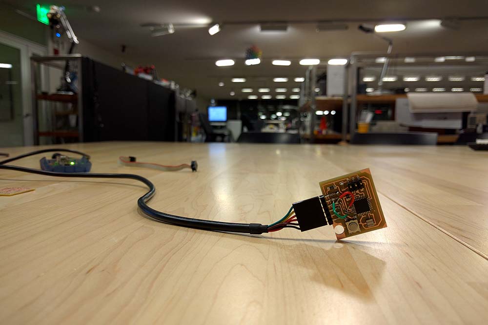 This code can actually run at the speed of the 50fps giving the output in real time to Arduino, which is amazing because Arduino itself won't be able to process these many frames while also picking out features of objects. I trained the camera to look at a redbox and output its values on Serial and here's what the values look like: