 I guess I have the highest amount of milling machine man-hours acrrued to my name by now. And if that sounds like I'm slow, this week's update is that I am finally feeling so comfortbale making boards and electronics in general. This week was about programming an application interface and connecting with an output/input device. I utilised this to make a part of my final project which is supposed to be a shape-changing table. In general, I already feel right at home making applications and I wanted to take this chance for another cool Design-Mill-Stuff-Program exercise.
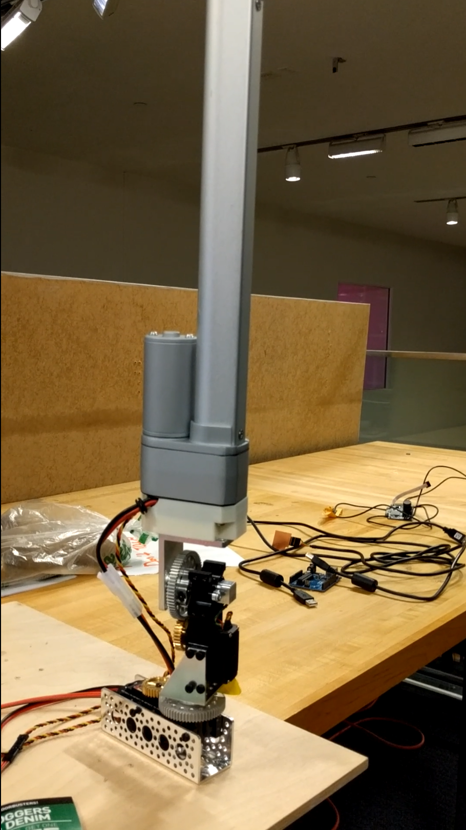 I am going to be driving four robotic arms in my project, so I made a prototype of one of these being driven from my board and being controlled
through a desktop application. The robotic arm in my case has a servo controlled Yaw, servo controlled Roll connection (mounted over the previous servo) and a linear actuator that is able to extend out.
These are high torque servos (HiTech 5685, with 7:1 gear ratio) that are holding a heavy linear actuator. The Linear acutator although not being shown in this assignment needs a 12V and a few amps of power supply whereas the servos need a power supply of 5V and another few amps. That's a lot of current when all the motors operate under torque.
I am going to be driving four robotic arms in my project, so I made a prototype of one of these being driven from my board and being controlled
through a desktop application. The robotic arm in my case has a servo controlled Yaw, servo controlled Roll connection (mounted over the previous servo) and a linear actuator that is able to extend out.
These are high torque servos (HiTech 5685, with 7:1 gear ratio) that are holding a heavy linear actuator. The Linear acutator although not being shown in this assignment needs a 12V and a few amps of power supply whereas the servos need a power supply of 5V and another few amps. That's a lot of current when all the motors operate under torque.
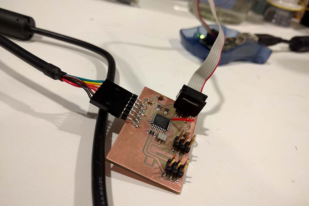
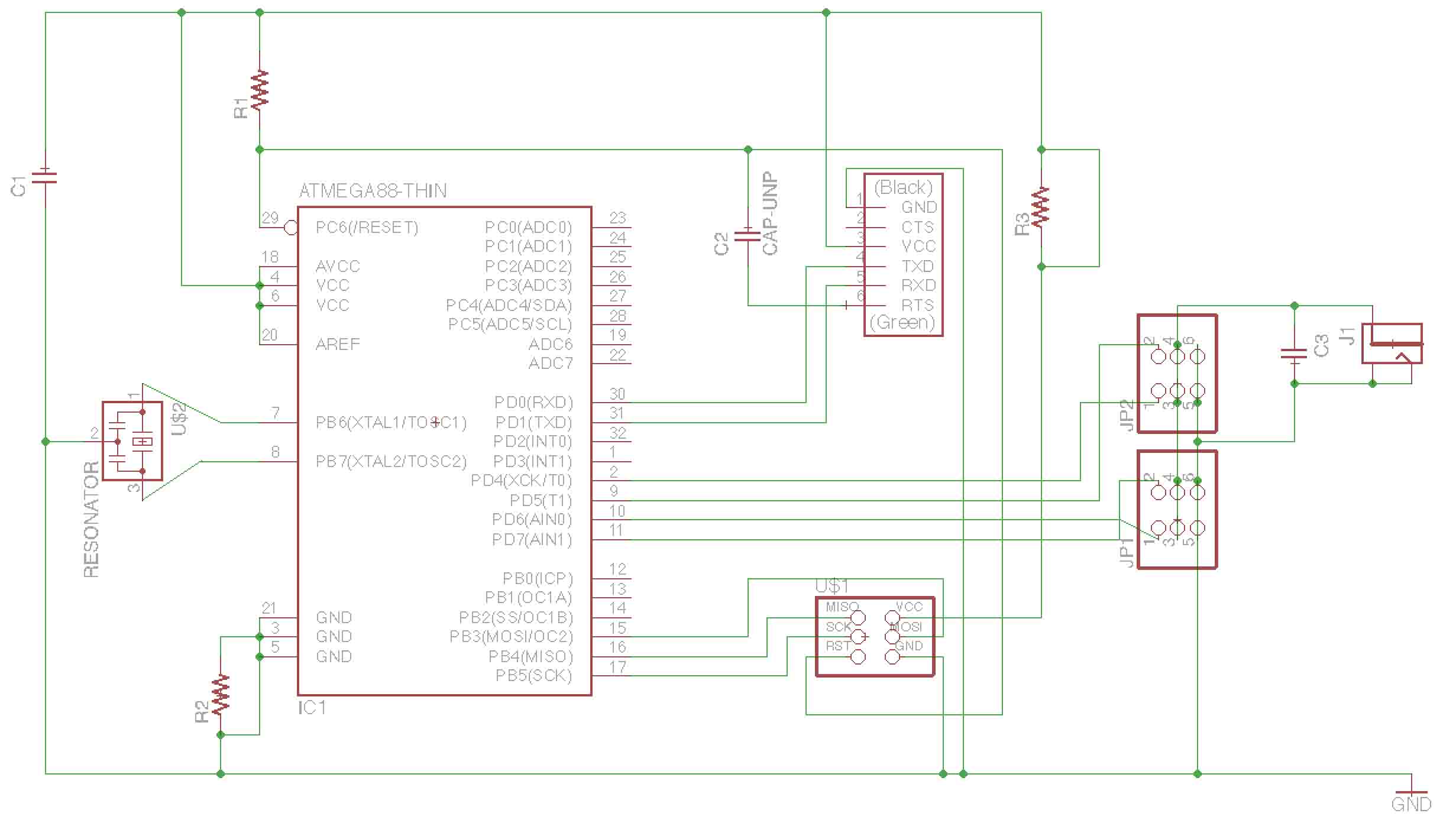 I decided to keep the ATMEL 328p as the on board MCU not only because of more pins but also test the small bridge/platform that I'd be finally using in the project. However, I didn't really need to use this chip at this point of time as is obvious from the schematic that I was breaking out most of the pins apart from some Digital Pins to drive Servo control pins.
 The servos have internal H-bridges, so unlike the steppers they don't need such external components. I designed the schematic in Eagle in under 15 minutes and subsequently did the routing puzzle. The servos that I have here (these are not continous rotation servos) can draw a lot of current under the load and I'm using external power for the servos and only have the control pins connected with the MCU. The MCU is already powered through the FTDI cable.
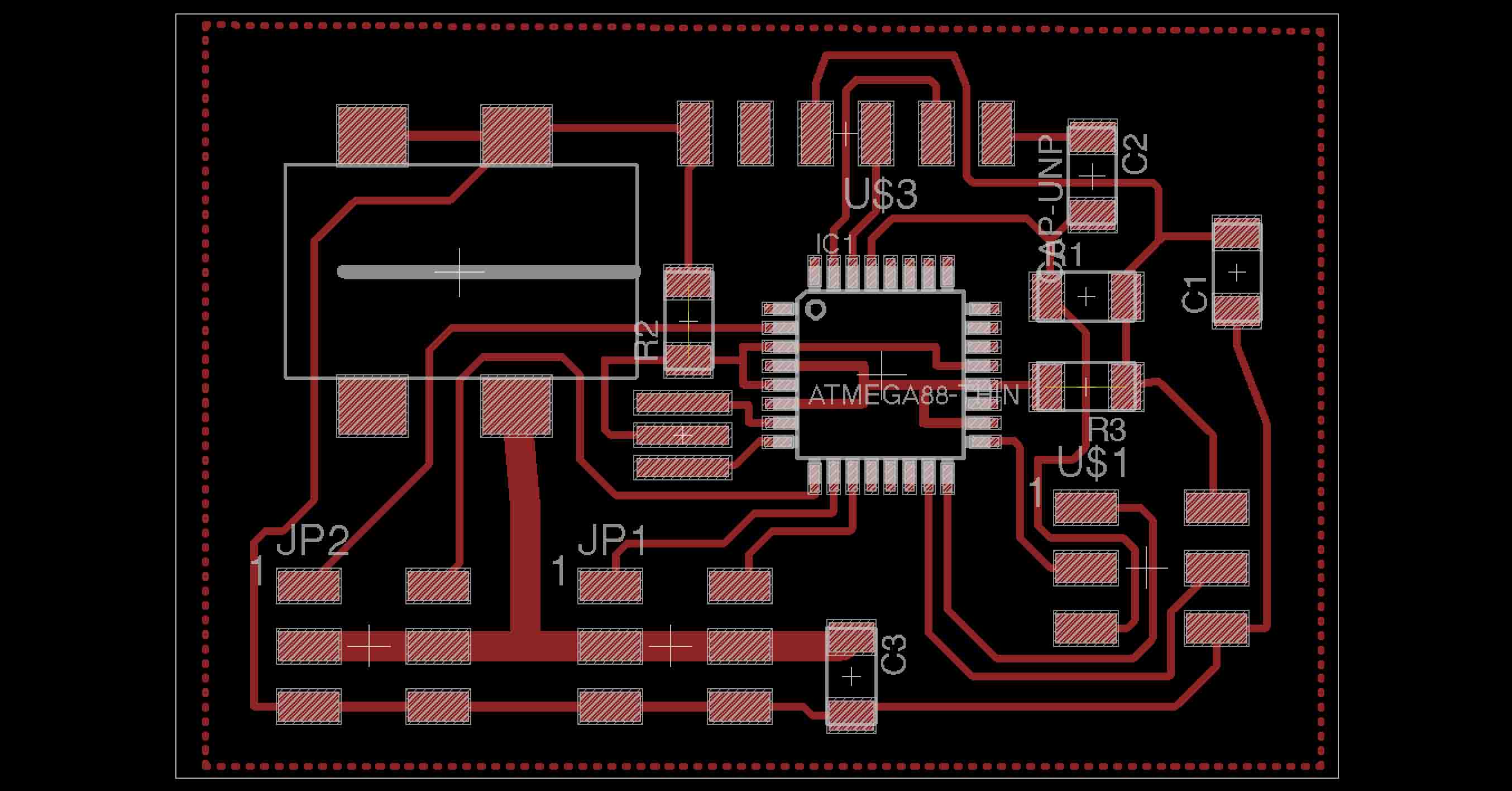
Since it was going to be a lot of current, instead of keeping the usual 0.016" traces, I decided to make bigger traces for the servo headers i.e. 0.05". Also, since I was going to dumping a lot of current int the ground, instead of using the traces, I decided to keep a ground plane on top of the board as well. This is done in Eagle by
Selecting the Polygon Tool >
Select appropriate Width and Isolation ( in my case it wach 0.01" and 0.05" respectively)
Change the name of the Polygon using Name tool to GND or whatever name your ground traces carry in the circuit
Drawing the polygon around the routed circuit
Tools > RatsNest
and it will give you a ground plane. You might have to tweak the values of Width and Ground Plane to get the right plane for you.
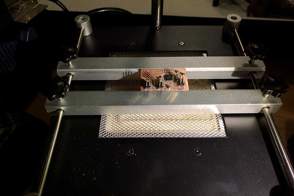 I milled the board and the traces didn't seem to come out so well from the Modela 2 this time around. I scraped the coper using the iron rule until it was clean but saw a lot of traces not there because they were too short in length. While this was fine since I was not losing any actual pins in use but the quality of the board and the remaining traces itself was miserable. I tried to solder manually using the soldering iron on this board and failed since a couple of traces came off.
My next attempt at milling was on the other Modela machine which seemed to work much much better. I think this voodoo magic is due to better sacrificial layer and new enmill. I couldn't solve this on the other Modela previously but this machine actually is able to give much finer traces even for the short unconnected ones.
I milled the board and the traces didn't seem to come out so well from the Modela 2 this time around. I scraped the coper using the iron rule until it was clean but saw a lot of traces not there because they were too short in length. While this was fine since I was not losing any actual pins in use but the quality of the board and the remaining traces itself was miserable. I tried to solder manually using the soldering iron on this board and failed since a couple of traces came off.
My next attempt at milling was on the other Modela machine which seemed to work much much better. I think this voodoo magic is due to better sacrificial layer and new enmill. I couldn't solve this on the other Modela previously but this machine actually is able to give much finer traces even for the short unconnected ones.
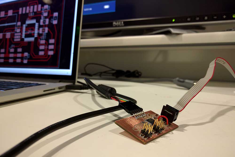
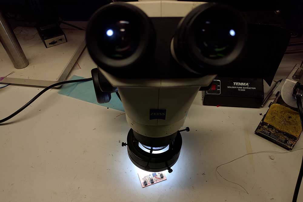 Subsequent to milling, I soldered the components using the solderig paste and reflow oven this time. The process was a breeze and I could now processed to programming stage. The programming stage went fine with the Arduino IDE (Settings: ATMEL 328p chip, External Oscillator: 20 MHz, Use Bootloader: Yes) and I was able to program with the FTDI cable after successfully burning the bootloader. A note of caution is that the RTS pin of the FTDI cable should definitely be connected to the RST pin of the chip (put a 100nF cap in between for isolation) or else it won't program (speaking from experience when I forgot to use this pin while I was looking at Neil's schematics and board layouts ; ) ).
I designed the interface in openFrameworks, which is a C++ toolkit and wraps several commonly used libraires together. The latest version at the
 time of writing this post if 0.9 and is very very cross-compatible. I made a small wireframe model of the base servo that rotates on yaw angle.
the top mounted servo over this rotate of the roll axis and the representation shows just that. This is not bidirectional yet but I'd love to have a feedback loop in between that is able to also adjust these wireframe virtual models based on the real world position.
time of writing this post if 0.9 and is very very cross-compatible. I made a small wireframe model of the base servo that rotates on yaw angle.
the top mounted servo over this rotate of the roll axis and the representation shows just that. This is not bidirectional yet but I'd love to have a feedback loop in between that is able to also adjust these wireframe virtual models based on the real world position.
openFrameworks has an inbuilt support for serial comm. which I decided to harness for sending messages for virtual moodel-servo rotation correspondence. On the ATMEL 328p side, you'd need to take care of what you're sending. The Serial comm. here basically treats all data as ASCII, so if you're planning on sending ints from your interface application, you'd have to break them into small bytes and receive them on the other side before rebuilding the int. In my case, I was sending char codes and decoding the same for motor rotations. Here's how the output looks like: