Objective
Integrate the units into one project.
Design ideas
I wanted knew that I would not be able to complete the project I initially proposed. I decided to built a cat toy/house instead. At the moment my cat lives in a cardboard box:
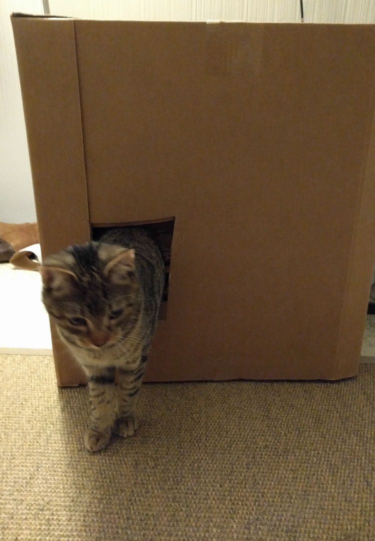
I wanted to make him a new house that would also entertain him. The step into the house should have a touch sensor, this sensor will trigger some kind of cat toy. I had a few ideas for the cat toy part:
- a servo motor to jerk around a bunch of feathers (no, too fragile)
- a stepper motor to roll up a rope (no, would probably get tangled up quickly)
- sound and light (no, too annoying for me)
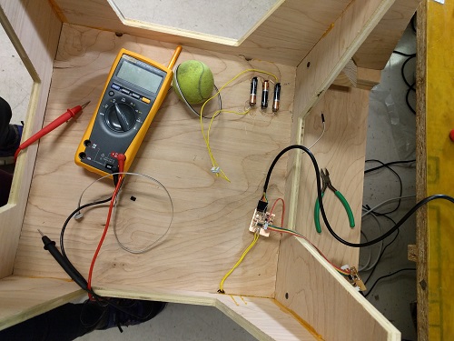
A while back, I found a project where a servo motor was used to move a ping pong ball. I decided to test, whether I coudl use a motor+ball combination to build my cat toy.
I wanted to make sure that I had a firm grasp (haha) of all the skills I needed for my final project before tackling everything at once:
- wooden frame: from CNC week
- cat toy: servo from output week
- touch sensor: input week
House
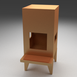
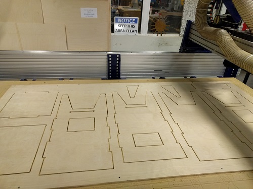
I modeled a quick mock up of the design of the house in blender (make sure to turn on cycles render for rendering). Based on this design, I then used Rhino to make profile cuts for milling:
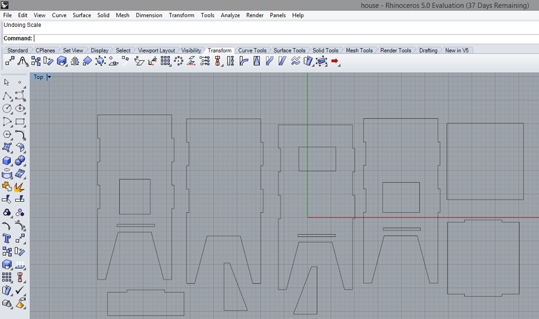
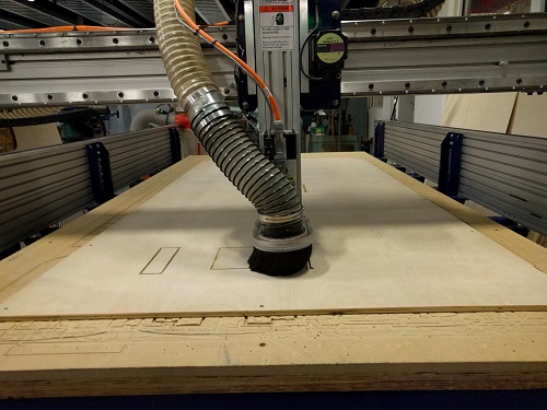
I added dog bone shaped fillets to all the inside corner of joints using the "Fillets" tool in the shopbot software (0.25in endmill, 10000rpm spindle speed, 90in/min feed rate, 40in/min plugne rate). I used the shopbot to mill the pieces out of birch plywood ($40 for a 4x8 feet piece from home depot). Make sure to do small, internal cuts first and then cut out the bigger shapes around them. Milling took around 30min overall.
The bottom of the cuts came out lookin quite rough, I sanded down the edges by hand:
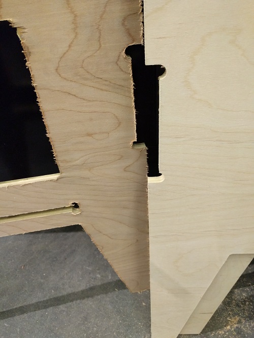
The pieces are held together by wood glue and wood screws (seems to be very stable).
Cat toy
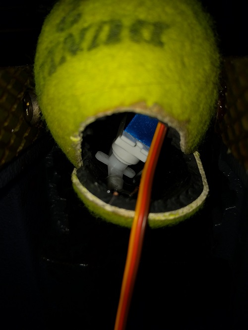
I cut open a tennis ball with a utility knife (the tennis ball was clamped down! Don't hurt yourself!) and glued down the servo motor inside. This resulted in only a very small wobble. For a bigger wobble, the rotation of the servo motor should move the center of mass of the tennis ball. I tried to achieve this by adding weights (scrap metal) to the bottom of the ball and to the side of the servo motor:
Programming
I started with my capacitive touch board from week 9: The functionalities I included are:
- a servo motor
- a button
- external power supply (three AAA batteries in sequence to generate 4.8V)
- capacitive touch sensor
For programming, I combined my code from the inputs and the ouputs week:
//                        attiny85
//                   reset -+---+- power
// (on while touching) pb3 -+*  +- pb2 (toggled by touch)
//       (touch input) pb4 -+   +- pb1 (fading while touching)
//                  ground -+---+- pb0 (fading always)


//                        attiny44
//                      power -+---+- GND
//                  10 -  pb0 -+*  +- pa0 -0
//                     9 -pb1 -+   +- pa1 - 1
//                 reset -pb3 -+---+- pa2 -2
//                     8 -pb2 -+*  +- pa3 -3
//                     7 -pa7 -+   +- pa4 -4
//                     6 -pa6 -+---+- pa5 -5


int servo = 6;
int calibration = 0;
int previous;
int tPulse        = 4000;         // Total pulse length on 1 Mhz clock
int hPulse        =   60;         // High pulse time (60=0deg -> 280=180deg)
bool Dir          =    1;         // servo direction
int randomval = 0;
int fadeval = 0, fadestep = 1;
int val = 0; //define button state
int lastval = 0; //define button state
int counter = 0;
int counter2 = 0;
const int button = 8; //pin with the button, duh


void setup()
{

  pinMode(servo, OUTPUT);
  pinMode(button, INPUT_PULLUP);
  delay(100);
  //calibration to find out what the pin looks like when you don't touch it
  for (int i = 0; i < 20; i++) {
    calibration += chargeTime(PA3);
    delay(20);
  }
  //+4 to round correctly
  calibration = (calibration + 4) / 20;
}


void loop()
{
//button code
  val = digitalRead(button);


   if (val == LOW && lastval == HIGH) {

    while (counter <= 500){


  digitalWrite(servo, HIGH);                // Set pin high to start pulse
  delayMicroseconds(hPulse);                // High pulse angle data
  digitalWrite(servo,LOW);                  // Set low for the rest of pulse
  delayMicroseconds(tPulse-hPulse);

  if (hPulse < 280 && Dir == 1) hPulse+=10; // Rotate servo to 180 degrees
  else if (hPulse >= 280 && Dir == 1){      // servo hit upper limit
    hPulse = 280;                           // Keep servo angle in bounds
    Dir=!Dir;                               // Switch direction
  }
  if (hPulse > 60 && Dir == 0) hPulse-=10;  // Rotate servo to 0 degrees
  else if (hPulse <= 60 && Dir == 0){       // servo hit lower limit
    hPulse = 60;                            // Keep servo angle in bounds
    Dir=!Dir;                               // switch direction
  }
  delayMicroseconds(500); // Give servo some time to move before giving it a new position
 counter++;
      }

    }


   else {

     digitalWrite(servo, LOW);


}
counter = 0;
lastval = val;


  //capactive touch code:

  int n = chargeTime(PA3);

  if (n > calibration) {

    while (counter2 <= 50){


  digitalWrite(servo, HIGH);                // Set pin high to start pulse
  delayMicroseconds(hPulse);                // High pulse angle data
  digitalWrite(servo,LOW);                  // Set low for the rest of pulse
  delayMicroseconds(tPulse-hPulse);

  if (hPulse < 280 && Dir == 1) hPulse+=10; // Rotate servo to 180 degrees
  else if (hPulse >= 280 && Dir == 1){      // servo hit upper limit
    hPulse = 280;                           // Keep servo angle in bounds
    Dir=!Dir;                               // Switch direction
  }
  if (hPulse > 60 && Dir == 0) hPulse-=10;  // Rotate servo to 0 degrees
  else if (hPulse <= 60 && Dir == 0){       // servo hit lower limit
    hPulse = 60;                            // Keep servo angle in bounds
    Dir=!Dir;                               // switch direction
  }
  delayMicroseconds(500); // Give servo some time to move before giving it a new position
 counter2++;
      }

    }


   else {

     digitalWrite(servo, LOW);


}
previous = n;
counter2 = 0;
  delayMicroseconds(500);
}
//this gives you the charge time of the pin that you touch
byte chargeTime(byte pin)
{
  byte mask = (1 << pin);
  byte i;

  DDRA &= ~mask; // input
  PORTA |= mask; // pull-up on

  for (i = 0; i < 16; i++) {
    if (PINA & mask) break;
  }

  PORTA &= ~mask; // pull-up off
  DDRA |= mask; // discharge

  return i;
}
// attiny85
// reset -+---+- power
// (on while touching) pb3 -+* +- pb2 (toggled by touch)
// (touch input) pb4 -+ +- pb1 (fading while touching)
// ground -+---+- pb0 (fading always)
// attiny44
// power -+---+- GND
// 10 - pb0 -+* +- pa0 -0
// 9 -pb1 -+ +- pa1 - 1
// reset -pb3 -+---+- pa2 -2
// 8 -pb2 -+* +- pa3 -3
// 7 -pa7 -+ +- pa4 -4
// 6 -pa6 -+---+- pa5 -5
//Define constants:
const int button = 8; //pin with the button, duh
const int LED = 2; //pin with the LED
int val = 0; //define button state
void setup() {
// put your setup code here, to run once:
pinMode(button, INPUT_PULLUP); //use the internal pullup of the microprocessor
pinMode(LED, OUTPUT); //LED pin will be our output pin
}
void loop() {
// put your main code here, to run repeatedly:
val = digitalRead(button);
if (val == LOW) {
digitalWrite(LED, LOW);
delay (100) ; // 100 microsecond delay
digitalWrite(LED, HIGH); // puts 5V on the LED pin
delay (100);
digitalWrite(LED, LOW);
delay (100) ;
digitalWrite(LED, HIGH);
delay (100);
}
else {
digitalWrite(LED, HIGH);
}
}
I cut a second touch sensor from copper foil using the vinyl cutter (also see week 9) and transfered it to the step of the house:
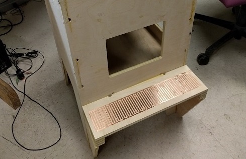
The power supply consists of three AAA batteries (1.5Veach) in sequence to supply 4.5V to the board (test the voltage that the batteries output with a multimeter).
Putting it all together
The cat toy attached to the house with touch sensor and button:
Potential improvements to project:
- patience when you are glueing!, the endproduct will look much neater!
- right now the wire between the ball is also a strucutral element, maybe add a sleeve around it?
- cushions on the inside
- something to cover the touch sensor