Objective
Make a microcontroller board with an output device.
Design - Servo
This is my second try to use an output device with one of my boards, I am describing my first (failed) attempt at the bottom of the page
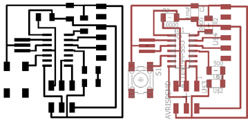
To make life easier for my, I am planning to use my blinking board from week 7 to do this weeks assignment:
Before I could program my board I first needed to figure out how my servo motor works. I found this website to be very helpful.
- In short:
- it is a small DC motor that is driven by pulse width modulation
- it can rotate clockwise and counter-clockwise
- the duration of the pulse sets the postion of the motor
- usually it can only rotate by 200degrees
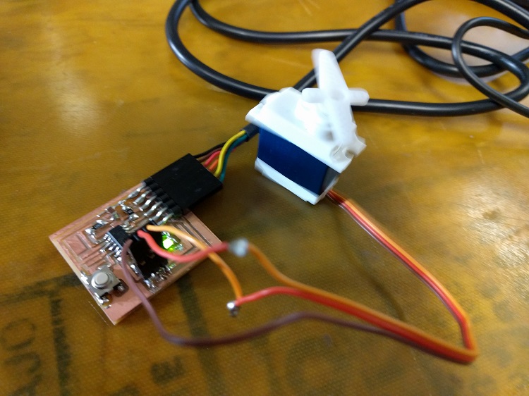
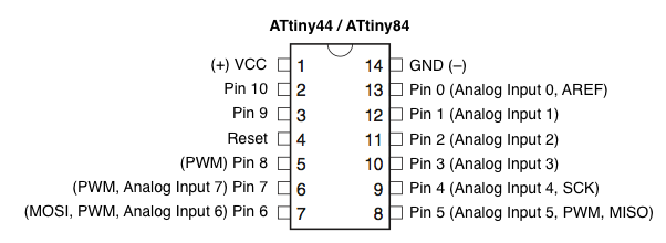
I want to use the 2x3 header to run a servo motor (HKSCM16-6 Single Chip Digital Servo (6V)). The servo takes 4.8-6V. The dark brown wire is GND, the red one is VCC and the orange one reads the output from the microcontroller (CONTROL). The bottom row of my 2x3 header has GND, VCC and MOSI. The MOSI pin on the attiny44 can be used as an output pin for a servo motor (it can pulse-width modulate). I decided to switch the VCC and CONTROL (S) pin of the servo motor:
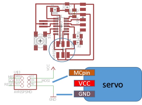
edit: I should have just disconnected the cables from the original header, switched VCC and S and connected the wires to a female 2x3 header.
Programming
I used arduino to write c code. To drive the motor poked around the internet a lot to see what other people had done before. I tried to use several arduino libraries for controlling servo motors without much success. I ended up using a piece of code I found here. I wanted to wiggle the motor for a few seconds after touching the button. With help from Andy Spielberg, I wrote a program in c code using arduino that does exactly that. I also used the arduino tutorials: Boolean and while loops:
//Define constants:
const int button = 8; //pin with the button, duh
const int LED = 2; //pin with the LED

const byte SERVO  =    6;         // Servo pin on ATtiny
int tPulse        = 4000;         // Total pulse length on 1 Mhz clock
int hPulse        =   60;         // High pulse time (60=0deg -> 280=180deg)
bool Dir          =    1;         // Servo direction

int val = 0; //define button state

void setup() {
  // put your setup code here, to run once:
pinMode(button, INPUT_PULLUP);
pinMode(LED, OUTPUT);
pinMode(SERVO, OUTPUT);
}

void loop() {
  // put your main code here, to run repeatedly:
val = digitalRead(button);

   if (val == LOW && lastval == HIGH) {

    while (counter <= 500){


  digitalWrite(servo, HIGH);                // Set pin high to start pulse
  delayMicroseconds(hPulse);                // High pulse angle data
  digitalWrite(servo,LOW);                  // Set low for the rest of pulse
  delayMicroseconds(tPulse-hPulse);

  if (hPulse < 280 && Dir == 1) hPulse+=10; // Rotate servo to 180 degrees
  else if (hPulse >= 280 && Dir == 1){      // servo hit upper limit
    hPulse = 280;                           // Keep servo angle in bounds
    Dir=!Dir;                               // Switch direction
  }
  if (hPulse > 60 && Dir == 0) hPulse-=10;  // Rotate servo to 0 degrees
  else if (hPulse <= 60 && Dir == 0){       // servo hit lower limit
    hPulse = 60;                            // Keep servo angle in bounds
    Dir=!Dir;                               // switch direction
  }
  delayMicroseconds(500); // Give servo some time to move before giving it a new position
 counter++;
      }

    }


   else {

     digitalWrite(servo, LOW);


}
counter = 0;
lastval = val;


}
Touching the motor does this:
Failed audio sampler:
Design
I am one of the EHS representatives in my laboratory, one of the most annoying part of the job is that I have to tell people to close their waste bottles. I use the phrase "close your waste bottle" at least three times a day! This week I want to make a microcotroller board with a button and a speaker. When you press the button it should say "Close your waste bottle." so I don't have to.
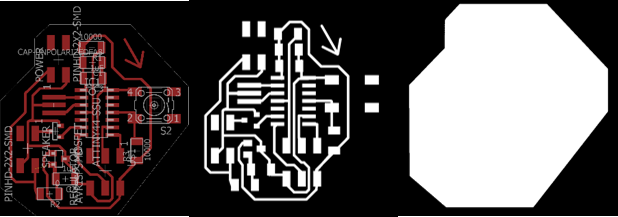
I found several tutorials (1, 2, 3) that describes how to use a microcontroller to play an audio sample. I made my schematic in eagle:
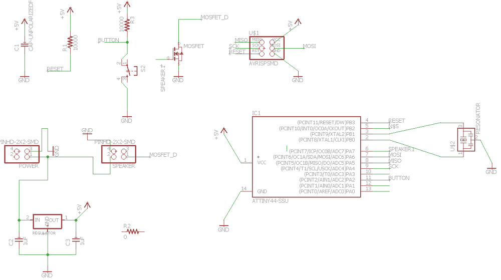
I am using an attiny44 microcontroller, a PSR-23F08S-JQ speaker, a button and I also included a battery connector. The speaker needs to be connected to PA7 of the attiny44 (it can be used for PWM output) and ground. The battery is connected to ground and to a regulator with an output of 5V. To make the board more compact, I will connect the battery and the speaker using two 2x2 headers.
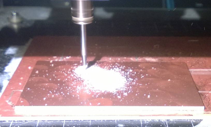
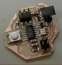
Milling and Stuffing
I used the modela for milling, no problems with milling or stuffing the board.
Programming
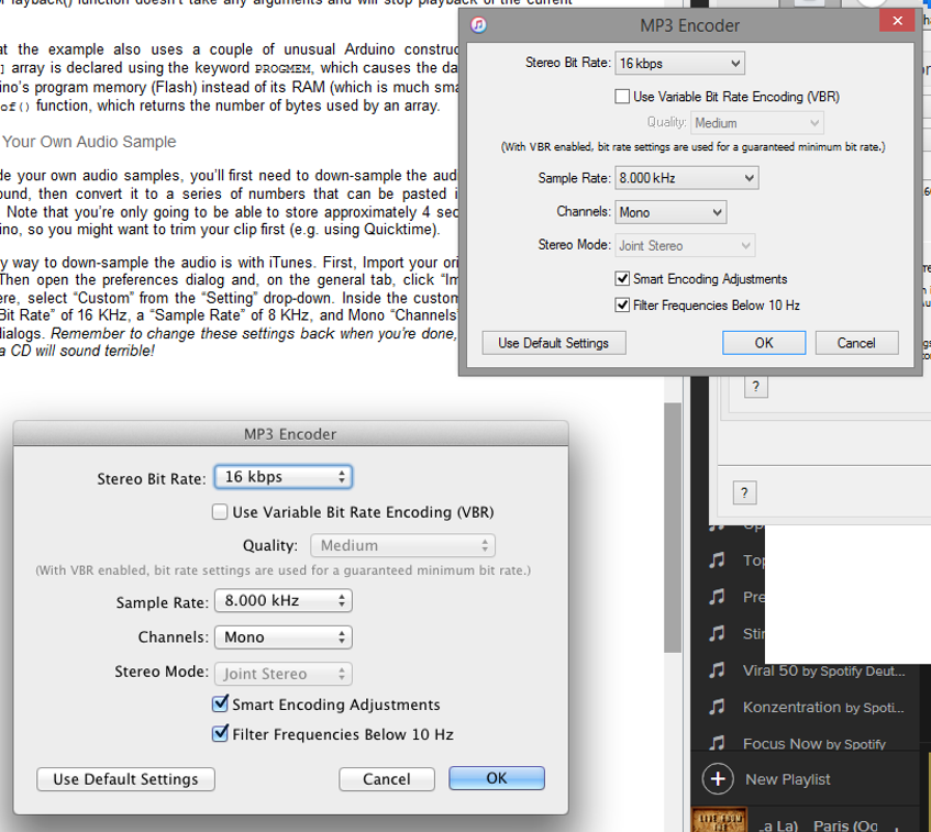
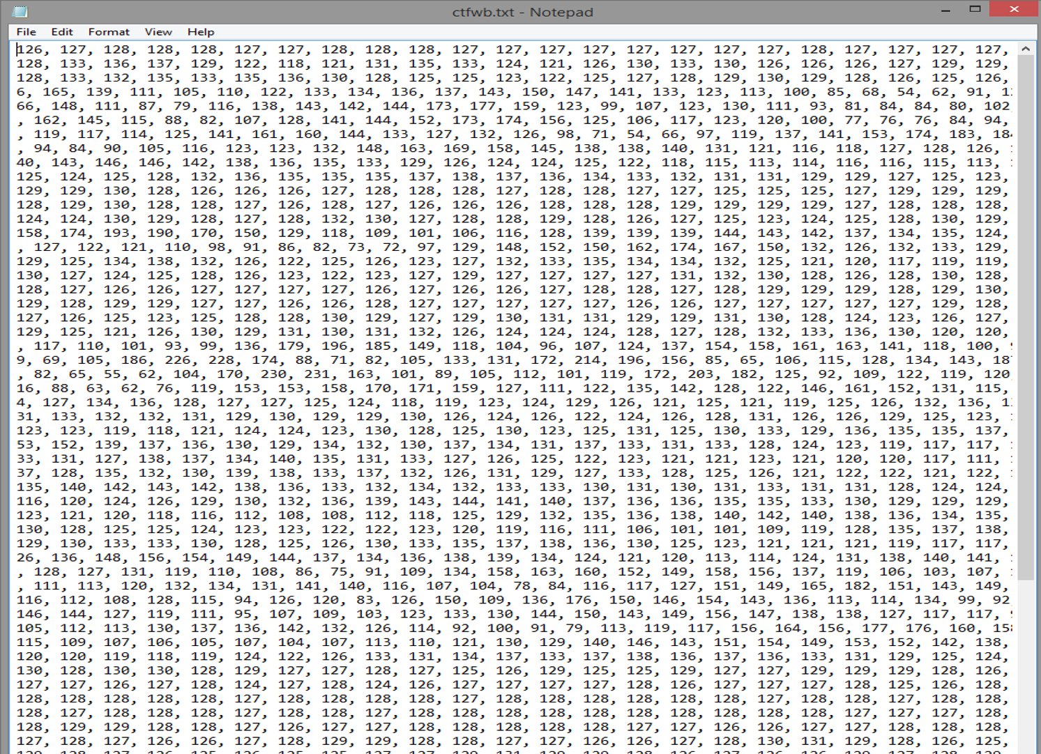
I downloaded a mp3 sample from google translate saying "Close your waste bottle". I then converted it to 8-bit mono, then you can convert the audio sample into a numeric code that can be pasted into the Arduino program. For this I downloaded an audio ancoder from highlowtech. The resulting audio code consists of three-digit numbers separated by commas:
Here are the audio files before and after b-bit conversion:
I used arduino to write my C code. My sketch is based on Micheal Smith's program. The only thing I changed, is the pin nubmer. He is using pin 11 on an attmega, I changed this to pin7 on the attiny44. I thought I was all set to start programming my board and connected it to my FabISP.
I couldn't upload my sketch, and I got a lot of error messages similar to : "error: 'TCCR2B' was not declared in this scope". After googling the issue, I realized that the original code which written for an attmega wich was using a timer 2 that our attinys don't have. The timer0 in the attiny44 is supposed to work similarly and I followed the suggestion to change all the expressions that refer to timer2 to timer0:
By the time, I had the solution it was too late for me to program and test the board. Working on it!
edit: I actually did not get it to work. I started wokring on moving a servo motor instead (I,ll be needing it for my final project)
Things I learned about trouble shooting electronics
- If you have no idea at all, start with an example board to get to know a new part.
- Using an output device and it's not working but you are not sure whether the problem lies with your board (or the program) or the output? Test the voltage on the output pin of the microcontroller, it it gives you 0V when it is supposed to be HIGH, there is a problem with the board (or program).
- To test your code: add softwareserial and write serial output at different points of your code to see where it fails/what it does.