Objective
This week we are adding a sensor to one of our boards.
Capacitive Touch
I wanted to make a capacitive touch sensor. I started with reproducing Neil's step response board. And then replaced the touch sensor with my own design and then replaced the program and the board with my own design.
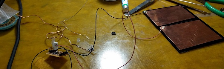
I had no problems with milling or stuffing the board. For the touch sensors I just used two medium sized pieces of copper foil that I soldered two wires to. Making this board was very good practice for learning how to male a capactive touch sensor. If anybody wants to make one of these, I highly recommend starting with a design that already works.
I then replaces the copper pads with two interdigitated electrodes (design in corelDraw) that I cut from the copper foil using the vinyl cupper (120gf force, 20cm/s) and transfered to a piece of leftover plywood:

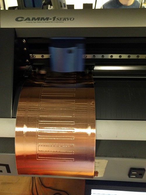
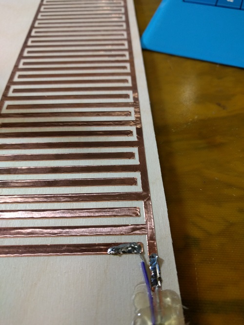
The copper doesn't stick to the plywood super well but it works with Neil's board and software.
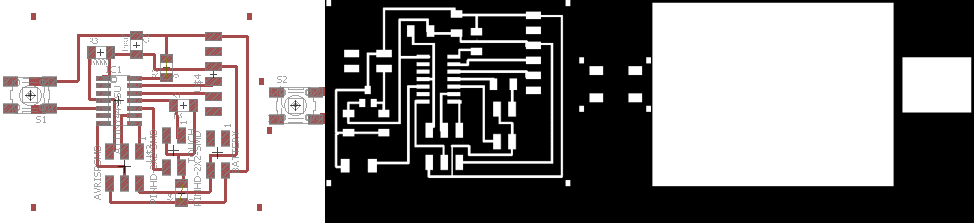
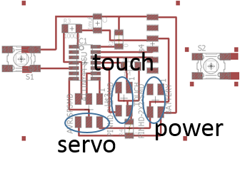
I then went ahead and designed my own board. I wanted to use this design for my final project. The functionalities I included are:
- a servo motor
- a button
- external power supply (three AAA batteries in sequence to generate 4.8V)
- capacitive touch sensor
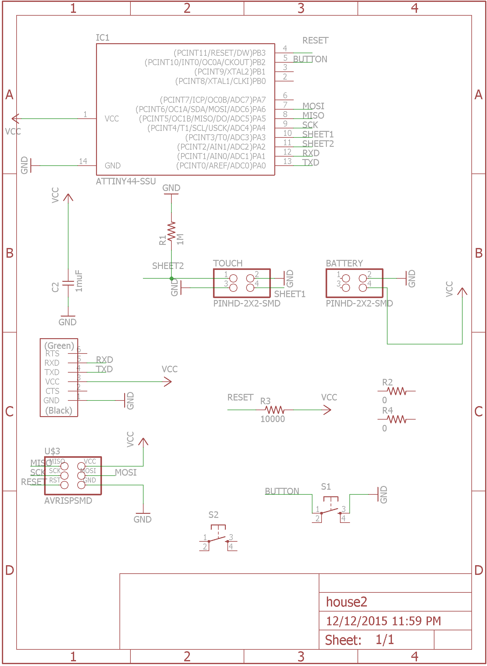
I studied the tutorial on capacitive touch sensors on High-Low-Tech and then designed my board in Eagle. The servo motor will be connected via a 2x3 header to VCC, GND and pin7 (MOSI pin), the button will be connected to pin5 and ground. The external power supply will be connected to VCC and GND, the capacitive touch sensor is connected to pin 10 and GND:
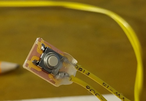
In my final project I want the board to be hidden, for this purpose I made a tiny board just for the button and then connected the button to the board using wires. I put hotglue around the soldered wires, the solder shouldn't act as a structural component:
Programming
Programming the board to use the capacitive touch sensor seemed to be really difficult at first. But it is actually suprisingly simple(thank you Jonathan for the explanations!). I do a calibration of the capacitive sensor suring the setup by sampling the charge time of the sensing pin 20 times and taking the average. In my loop, I measure the charge time against my calibration time. When I touch the sensor, the charge time changes and I am putting my output pin HIGH.
//                        attiny85
//                   reset -+---+- power
// (on while touching) pb3 -+*  +- pb2 (toggled by touch)
//       (touch input) pb4 -+   +- pb1 (fading while touching)
//                  ground -+---+- pb0 (fading always)


//                        attiny44
//                      power -+---+- GND
//                  10 -  pb0 -+*  +- pa0 -0
//                     9 -pb1 -+   +- pa1 - 1
//                 reset -pb3 -+---+- pa2 -2
//                     8 -pb2 -+*  +- pa3 -3
//                     7 -pa7 -+   +- pa4 -4
//                     6 -pa6 -+---+- pa5 -5


//Define constants:
const int button = 8; //pin with the button, duh
const int LED = 2; //pin with the LED

int val = 0; //define button state

void setup() {
  // put your setup code here, to run once:
pinMode(button, INPUT_PULLUP); //use the internal pullup of the microprocessor
pinMode(LED, OUTPUT); //LED pin will be our output pin
}

void loop() {
  // put your main code here, to run repeatedly:
val = digitalRead(button);
   if (val == LOW) {
     digitalWrite(LED, LOW);
     delay (100) ; // 100 microsecond delay
     digitalWrite(LED, HIGH); // puts 5V on the LED pin
     delay (100);
          digitalWrite(LED, LOW);
     delay (100) ;
     digitalWrite(LED, HIGH);
     delay (100);
   }
   else {

     digitalWrite(LED, HIGH);
   }


}
It works! Here is a short video that Eric took. I am touching the sensor with my face and I am reading the voltage between GND and my output pin: