Technologies Used
OpenSCAD was used to model the mechanical parts.
3D printing was used to fabricate the chassis and some fixtures.
Laser Cutting was used to make "caps" to secure some areas of the pen.
Machine Design Knowledge was used to integrate the mechanical parts.
Electronics Production was used to create the circuitboards.
Knowledge of Input Devices was used to make a temperature regulator.
Knowledge of Output Devices was used to control DC motors.
Embedded programming was needed to control the electronics.
Smart system integration was used to bring it all together.
Project Overview
NOTE: THERE IS STILL A SCAD FILE TO ADD. I WILL IT ONCE I HAVE ACCESS TO THE FILE ON MY DOWNED COMPUTER.
Well, here we are at last - the final project. As I'd stated previously, I originally wanted to make a quadcopter. However, realizing that a quadcopter would require a lot of domain-specific fine-tuning, didn't provide me any new functionality I couldn't already just buy, and was a conisderable engineering effort in the time alotted, I decided it would be better to spend the project doing something simpler and perhaps more useful. Discussing with a labmate, he pitched the idea of a 3D printing pen that could also cut - thus, allowing you to do both handheld additive and subtractitive manufacturing. Ideally, it's a pen that can do almost anything! I deicded that this could be an interesting space, as you could add more and more end-effectors to a tool (think: multi-colored pens) and get more functionality. Starting with two effects seemed like a good place to start. Thus, the goal of the device is to create an object which can both extrude PLA plastic as well as cut it with a dremel tool.
Prior Work
Of course, a 3D printing pen is not new. The 3Doodler predates it as the first 3D printing pen, along with Lix and some 3D printing pen prototypes I've seen in the Media lab. Handheld subtractive manufacturing is not new either, and Dremel tools are the most common example. On the flavor of additive and subtractive manufacturing, there was a project at UIST 2015 which did additive and subtractive manufacturing in a stationary printer with clay. The idea to do it handheld and with PLA is new.
Design
For this project, I designed the following artifacts, some of which are written about in greater detail in previous weeks.
- A chassis, which is the casing around the pen to hold all the motors, machinery, heating element, etc.
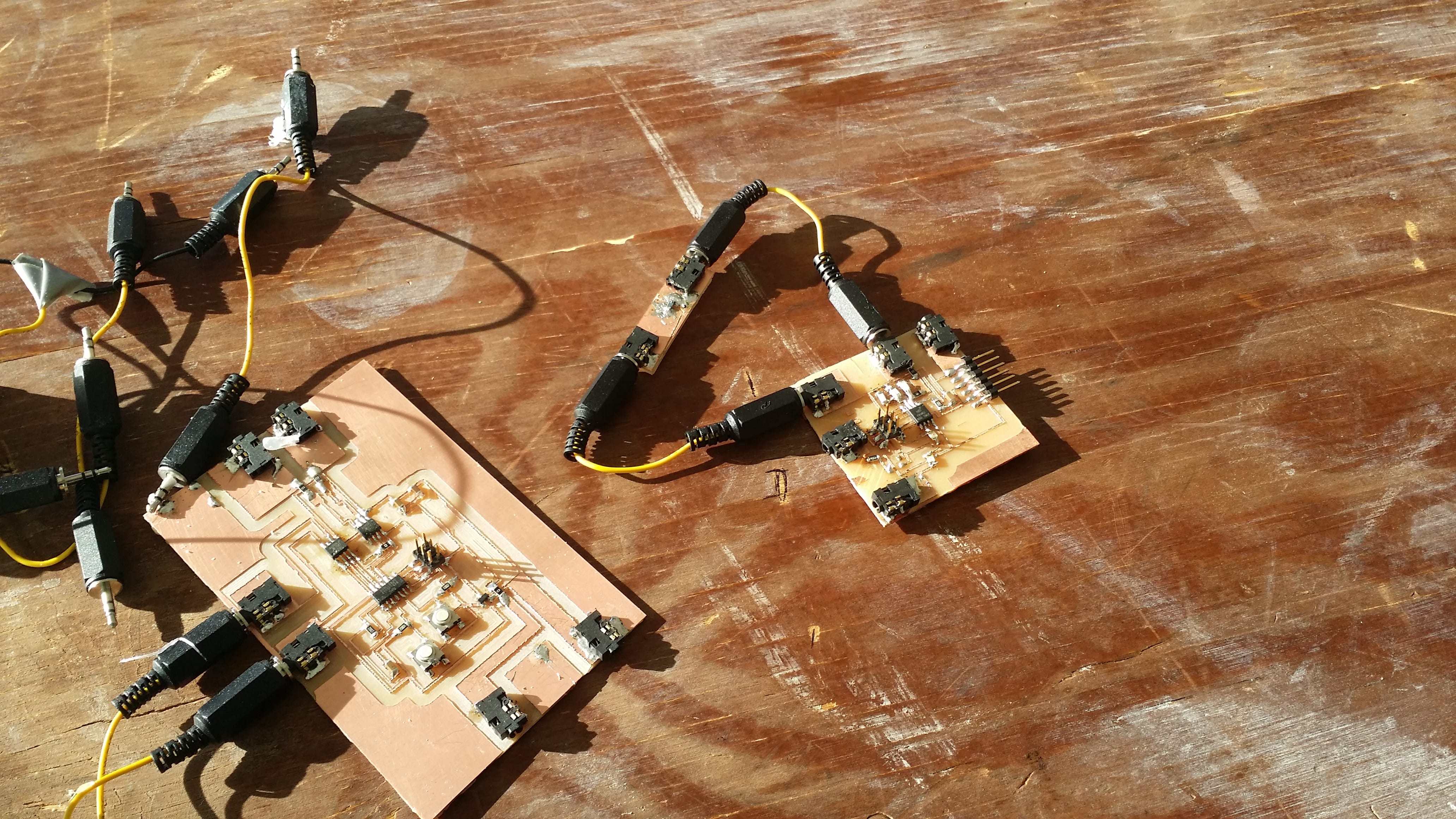
- Two circuitboards: one input temperature sensor for temperature regulation of the heating element, and one output board with two motors for extruding the filament and spinning the Dremel. These circuitboards are extended versions of Neil's designs
- Gears, dowels, and locking dowel caps when specific tolerances were not needed.
- Any extra casing needed to hold circuitboards and machinery in place.
- The system in which all the components talk to each other.
- The code for running on each board, also based off of Neil's existing code but modified and extended for my purposes.
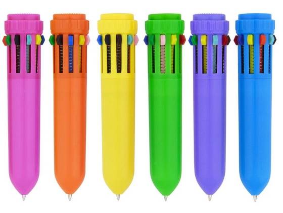
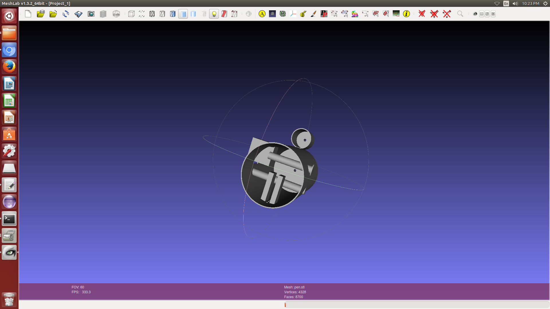
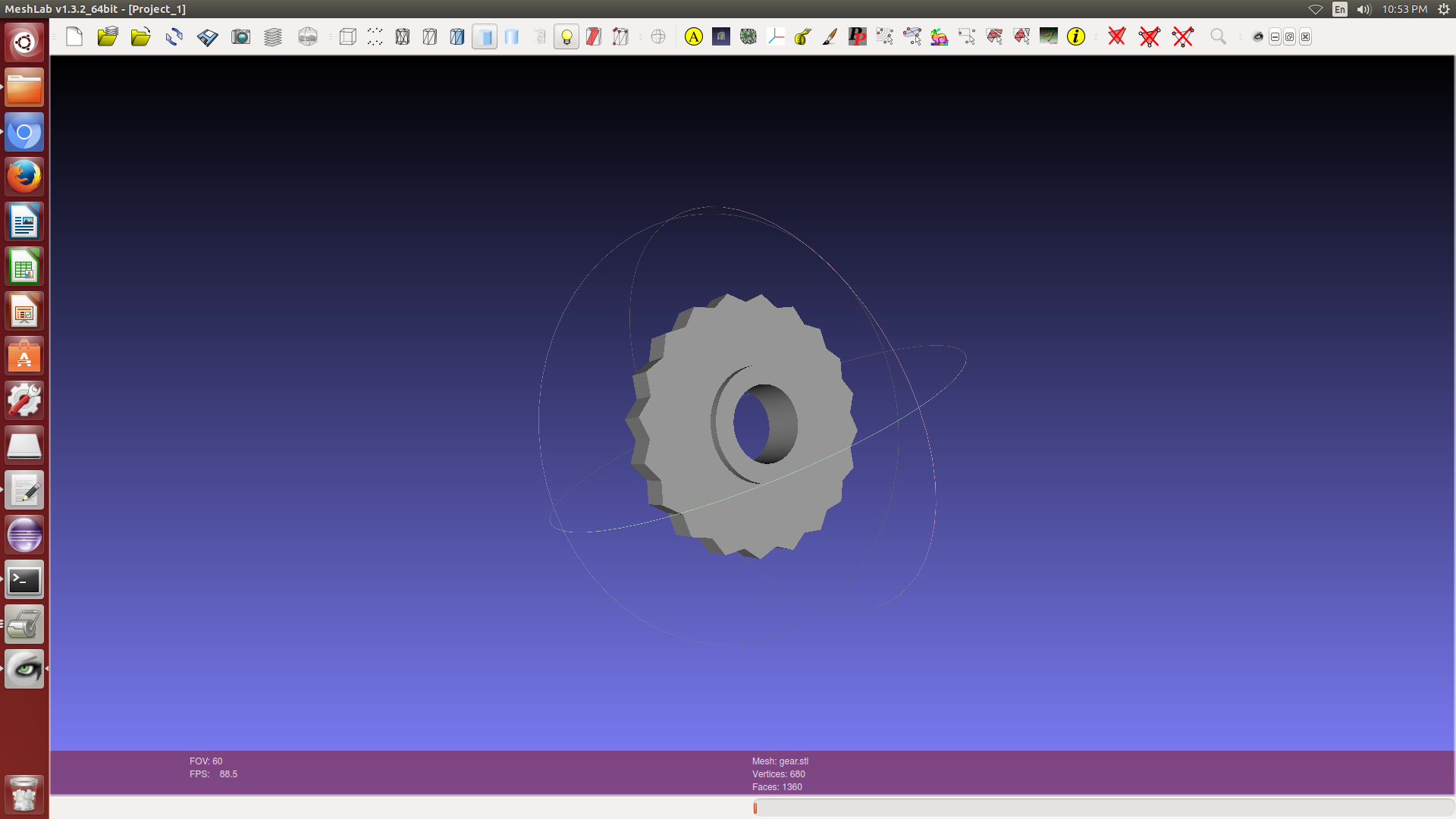
The chassis design and dowels can be downloaded here: stl, scad (COMING SOON). A rendering can be seen below.
Materials + Components
This project relied on the following components:
- Endur (RGD 450) was used for any of the 3D printed parts. This came from the MIT CSAIL printer supply. 180 grams of Endur were used to fabricate the chassis. This cost is estimated at around $60.
- A purchased, fitted drive shaft and ball bearing were used for the filament to rest upon. This was purchased from McMaster-Carr. These were $10 for the ball bearing and $6 for the drive shaft. I also purchased a cutting effector from McMaster-Carr for $4. These parts were purchased because I didn't know how to make a cutting end-effector or a ball bearing, and since I was already buying a ball-bearing I thought it was most appropriate to get a fitted drive-shaft with it.
- A DC motor was used to spin the extrusion gear. A second DC motor was used to spin the Dremel device. These came from the CBA shop.
- Acrylic was used to create caps for the top of the pen parts. This came from my lab, and cost < $10.
- PCBs were used to create the circuitboards. These came from the CBA shop.
- Circuitboards were stuffed with ATTiny44s, ATTiny45s, H-Bridges, thermistors, resistors, capacitors, LEDs, switches, N-MOSFETs, headphone jacks (for power transfer) and voltage regulators. These came from the CBA shop.
- A purchased heating element was used to heat the filament was it was extruded. This came from Amazon and cost $20. This was purchased because I didn't know the appropriate material to use otherwise to heat a component.
System, Subsystems, and Fabrication Decisions
First, an electronics system diagram can be seen below.
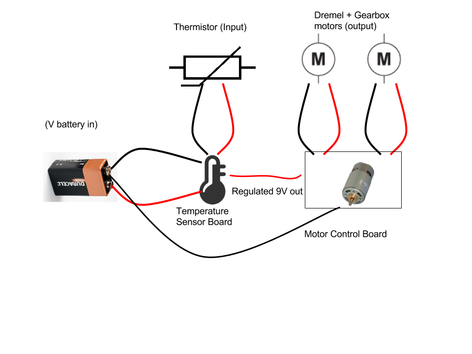
Let's examine what is happening here. First, we have a 12V power supply, powering the regulator board. The regulator measures when the temperature is too hot, above a safe working temperature. This is important because if the temperature of the heating filament gets too hot it can start to damage certain other aspects of our device, including the chassis or PCBs. Since the heating filament can heat up to 1200 degrees F (And fast, too!), it can melt solder joints, ruin microcontrollers, and even eat through the Endur. I don't have data on when Endur melts, but I know that PLA melts at 320 degrees F, so I figured it was a safe bet to clamp the temperature of the device to be around 340 degrees Fahrenheit.
When the temperature is too high, the regulator outputs no voltage. This means the filament stops heating, and the motor board is not powered. When the temperature is in a safe range, though, both the filament and motor board are powered. This means the material can be extruded. The only regret I have is not putting two output channels so the filament and the motor board could be controlled separately; after all, the motor board shouldn't work when the temperature is too low either.
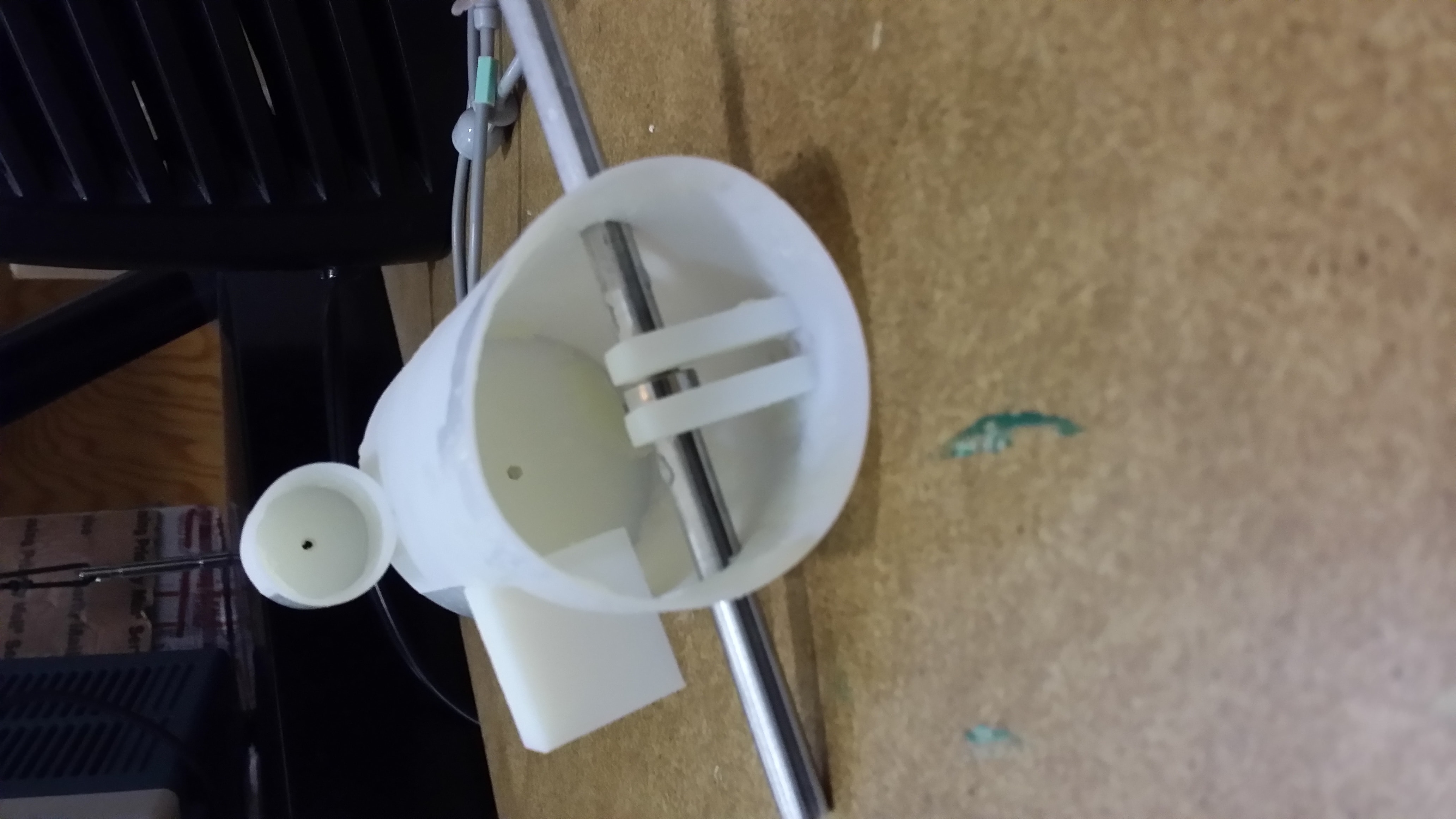
The chassis was fabricated using 3D printing, and has a simple mechanical design: a gear is spun and compresses some filament against a ball bearing while torquing it downward. Yes, I know this isn't a well designed gear, but it's not meant to spin with another gear, but rather to extrude material, so I figured it would be fine for that purpose. Endur was chosen to give the print some flexibility over the Vero materials and make it less brittle. I didn't want any critical components snapping.
Aside from a few press-fit components (dowel and caps) and one small component (the gear), you may argue that most of the chassis could have been casted. In fact, I tried to decide whether or not I should 3D print or cast my device. I think the correct answer in an ideal world would have been to cast it, but I went with 3D for two reasons. First, I was in a bit of a time crunch, and casting requires a lot more more manual startup time to make molds. Since I was only making a single pen, this wasn't a great time investment. Meanwhile, 3D printing just requires hitting the start button and cleaning off support. The advantages to casting, though, were access to better (cheaper, more durable, and better finish) materials and less cost in not needing support material. However, I had no experience with the correct casting materials for such a job (plastics?), probably would have required injection-molding since I had a thin chassis, and didn't think that Hydro or Dry Stone would have enough give to make a thin design such as the pen durable. Thus, I took the cheap 3D printing way out. With more time and skill, I would have gone with casting.
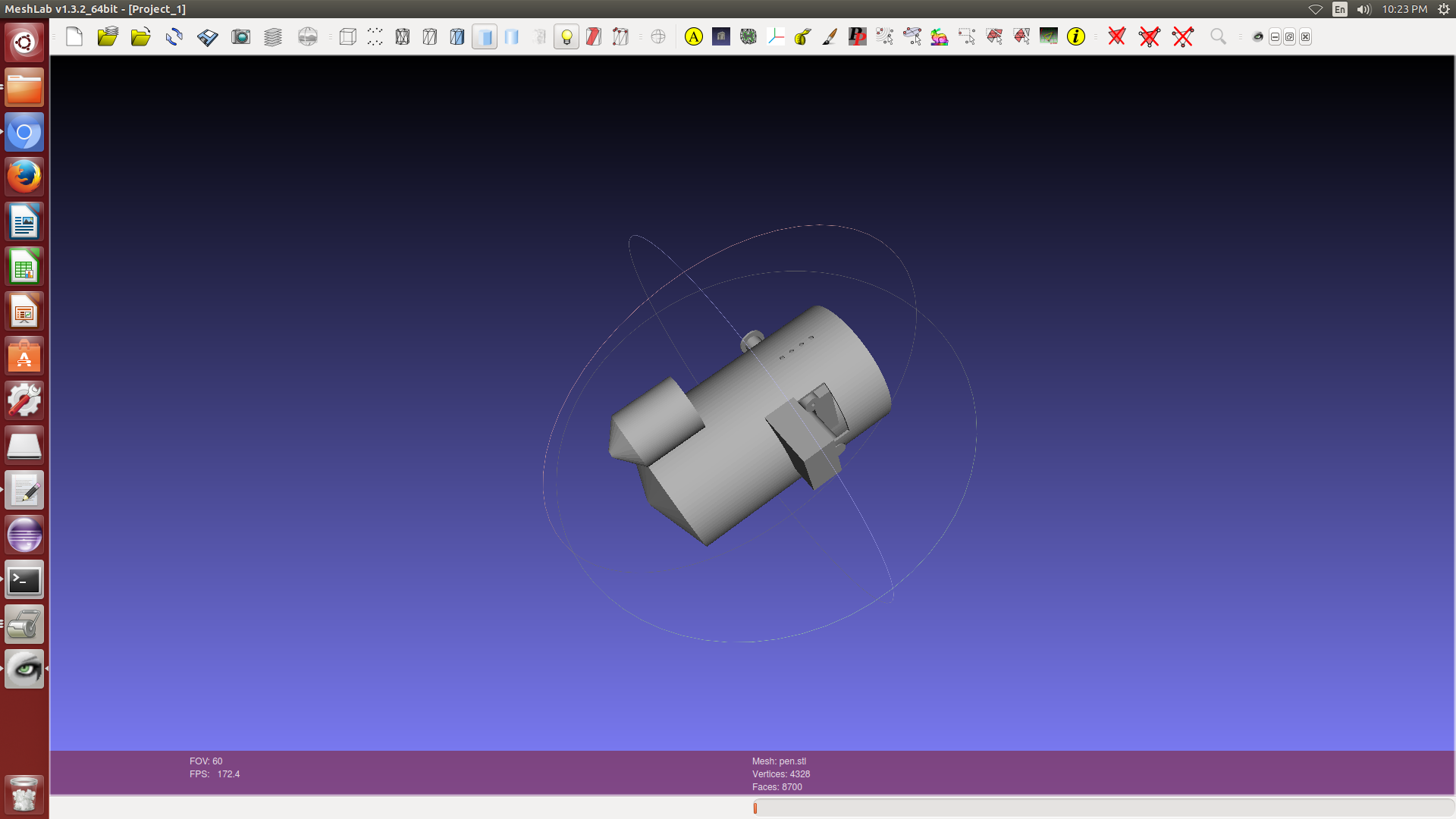
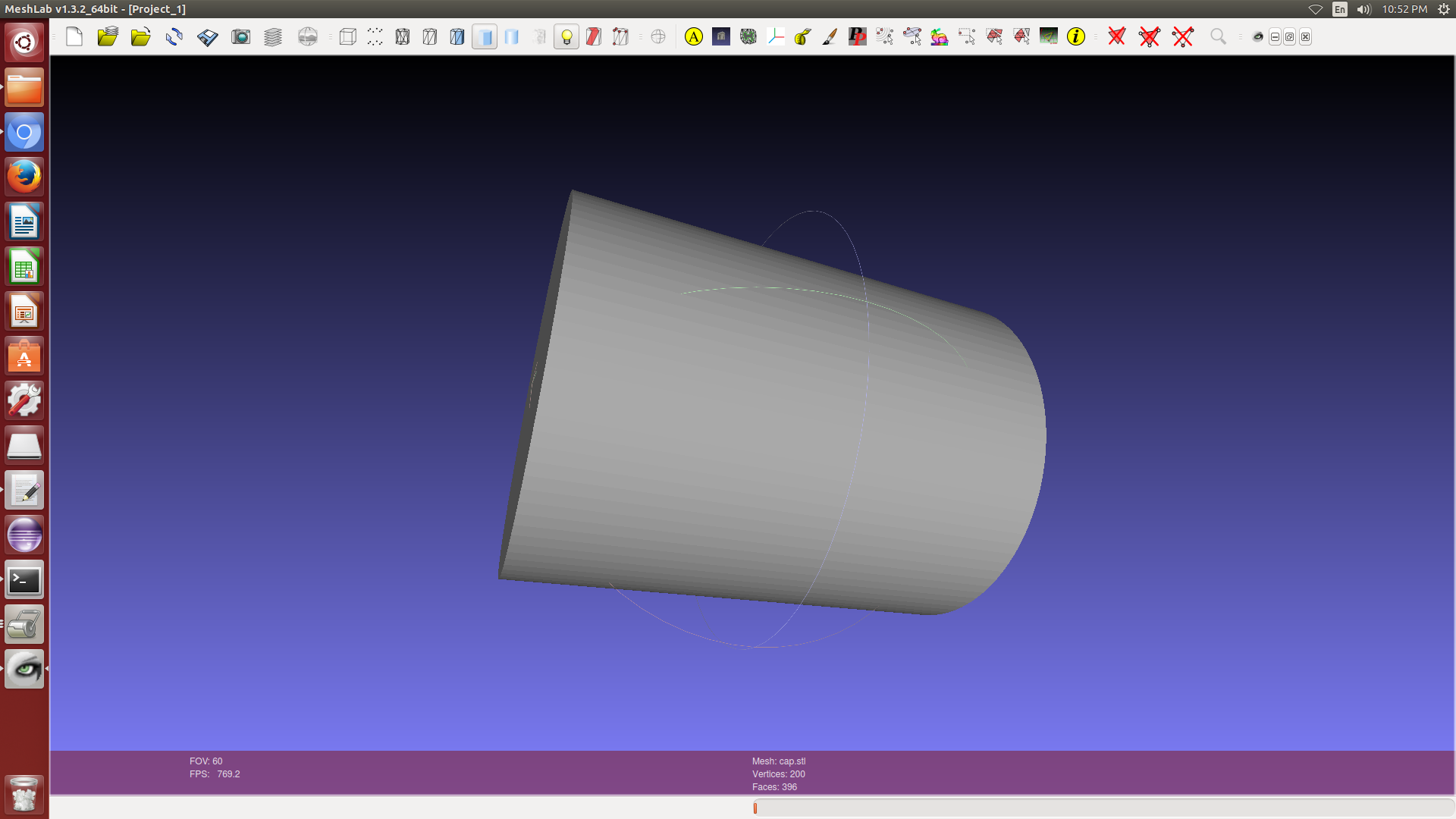
Top caps on the pen were created in acrylic, because it can be very quickly laser cut, is cheap, and has a very nice finish. The .svg for downloading the caps can be downloaded here
See the I/O weeks for more detail on the design decisions of those components. They were fabricated through board milling, soldering, and embedded C programming (using the avr libraries, not the Arduino wrappers).
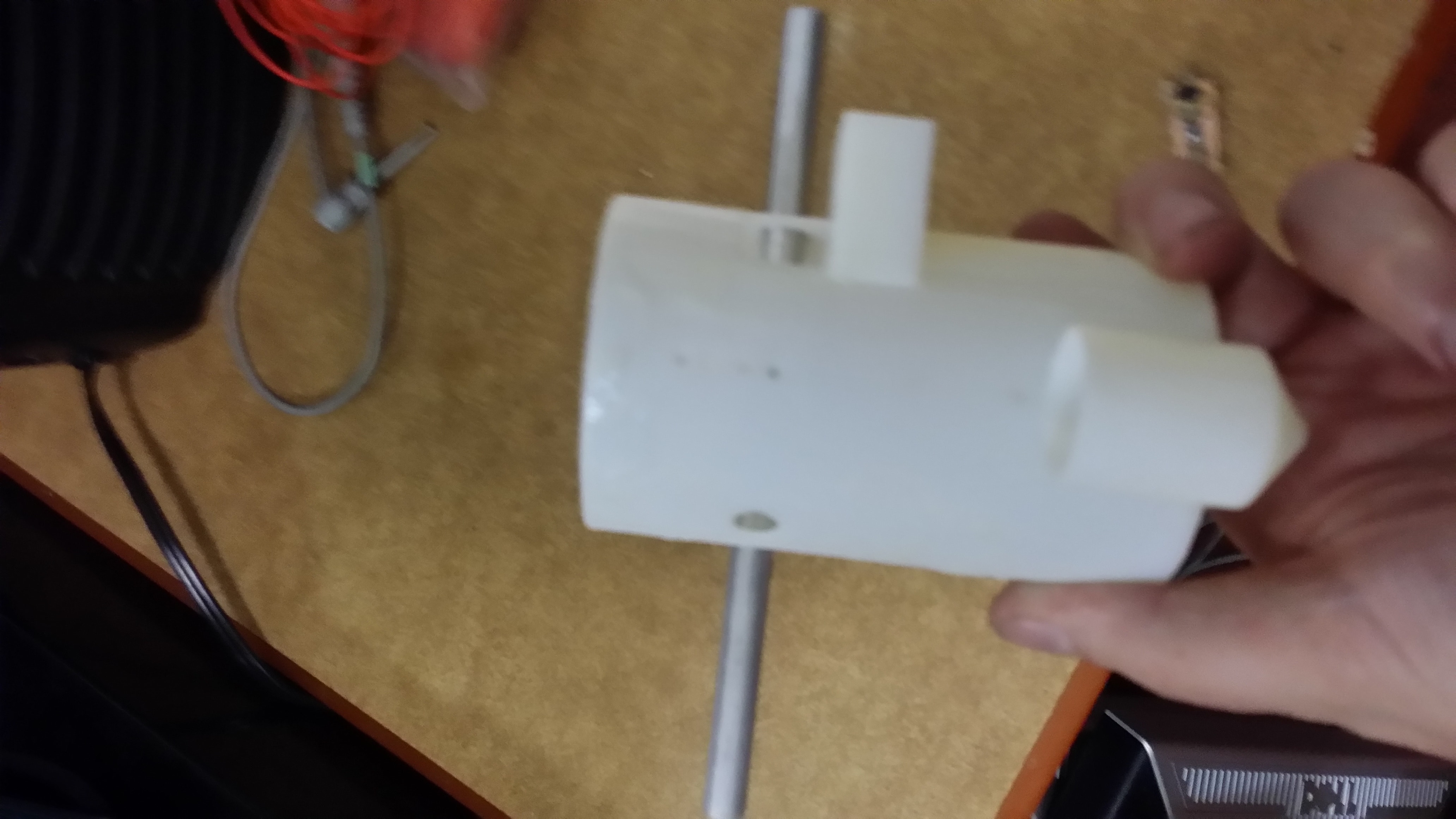
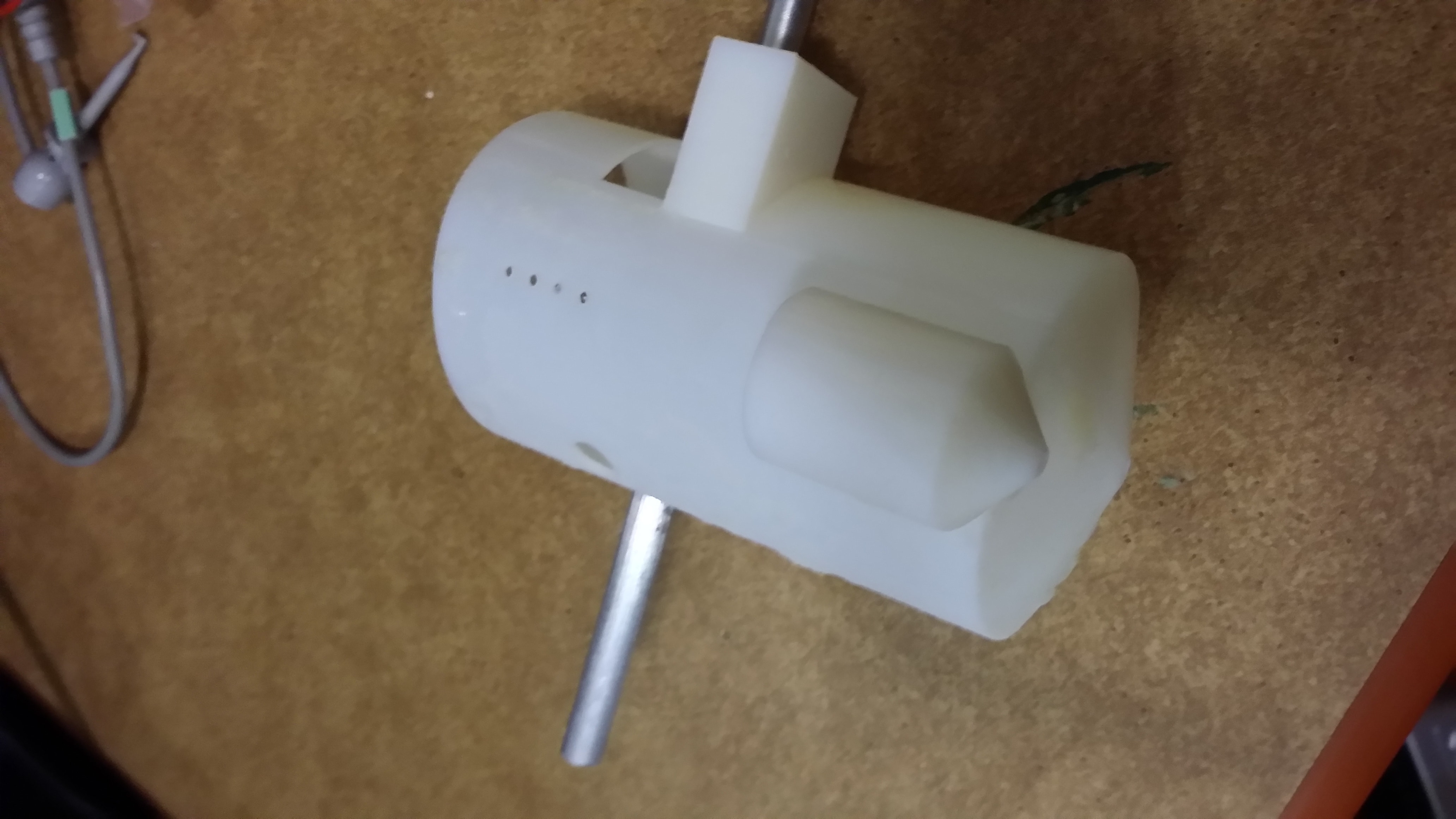
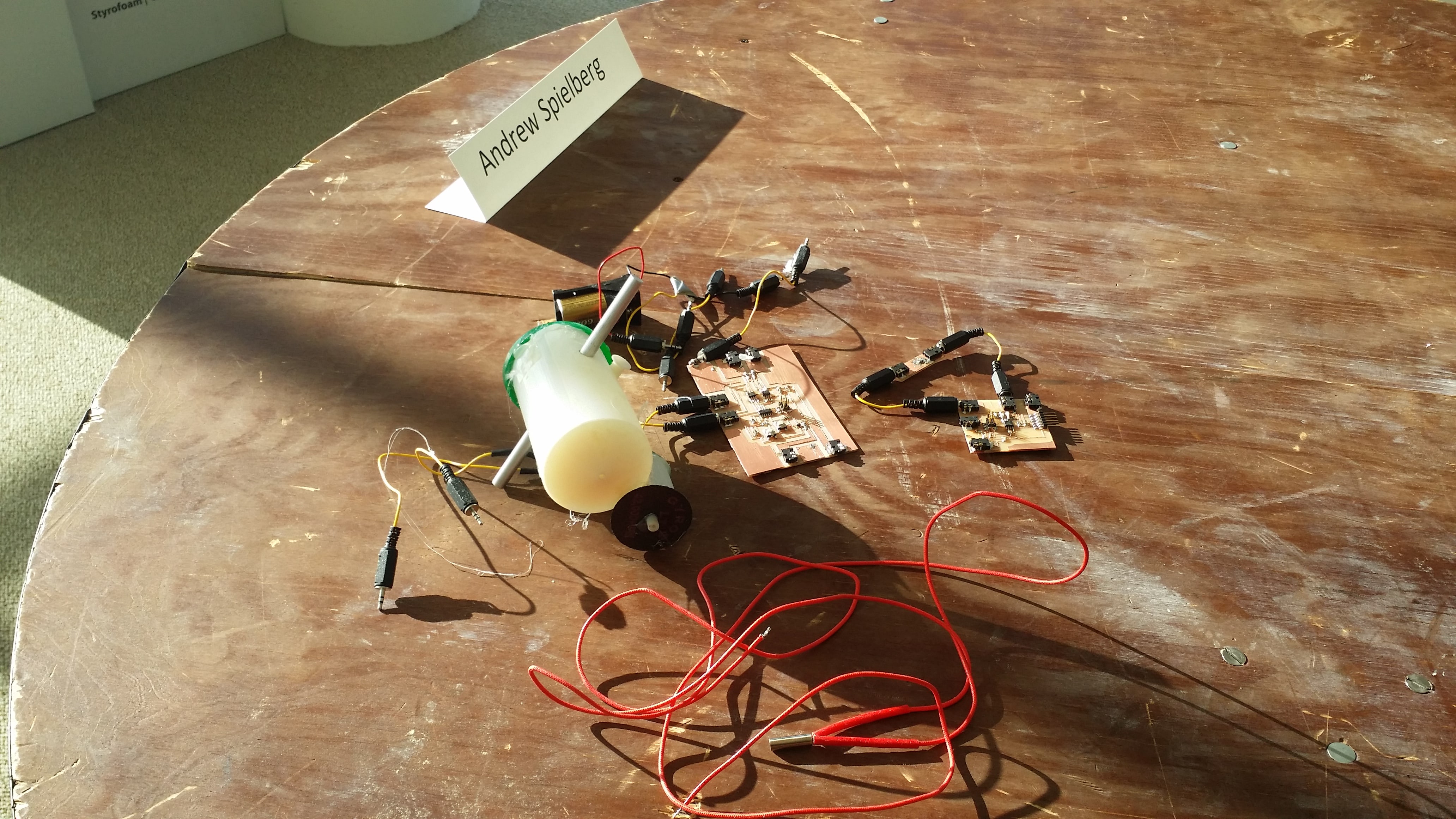
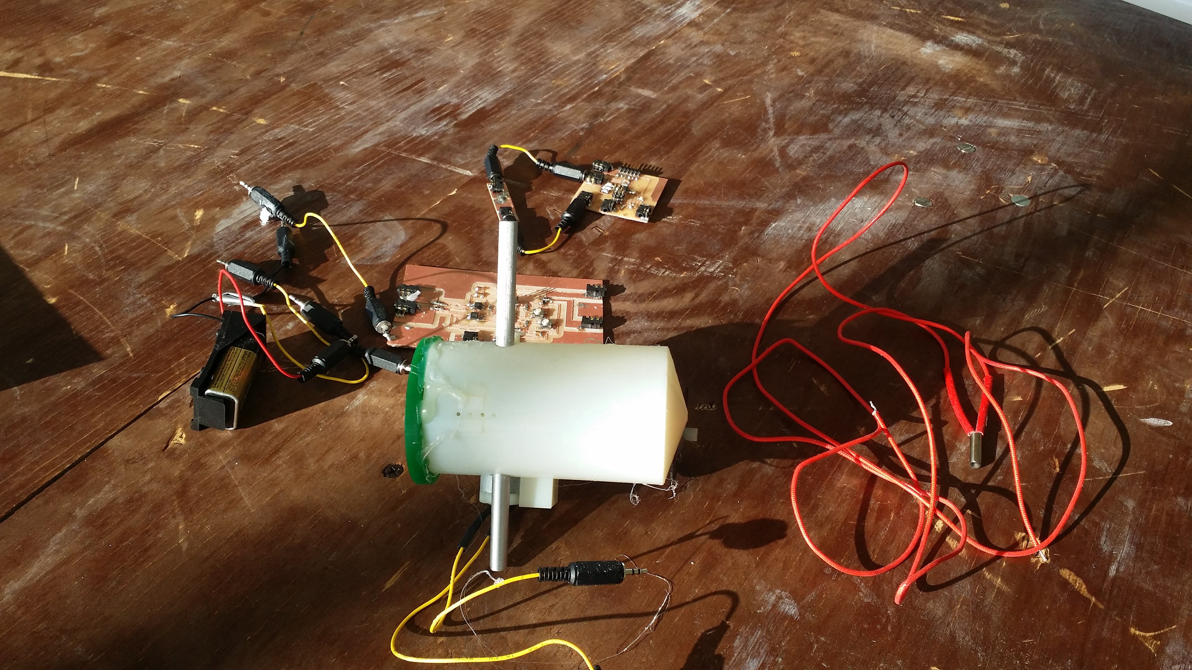
The full integrated pen design can be seen below, along with the electronic system.
Trial, Error, Testing, Evaluation, and Results
There are a few problems stopping this current project from working.
First, and most importantly is the lack of a heating element. Because of the fact that the temperature sensor is not working, I considered it too dangerous to add a heating element. Otherwise, that would accept the 9V output from the temperature regulator board and heat a metal tube, which I would add to the center of the pen. This tube would double as a guide for the extruded plastic. Without the thermal regulator, though, the pen (and likely the entire area around it) would melt - the heating element can reach temperatures close to 1200 degrees Fahrenheit with constant current. The heating element would probably also need to be PWM'd to slow its heating curve.
Second, the current motors I used do not have enough torque. the gear cannot spin because it cannot exert enough effort to spin the dowel (even though the dowel is light), and the dremel attachment is too weak to actually cut (although it spins). Beefier motors are needed to make this system work.
Third, the pen is overly flexible. Choosing Endur might have been a bad choice, I probably should have figured out how to cast the polyurethane or printed in a more rigid material. I also should have given it thicker walls for more staiblity. As it is, the exterior of the pen deforms, and more problematically, this causes the fixture holding the bearing and gear box aligned to wiggle, causing them to become unaligned.
Three errors were made that had to be fixed manually. While the pen was originally printed one-shot, the dremel holder had to be removed and replaced (and glued on) because I accidentally set its diameter to be the inner diameter of the motor shape, not the outer diameter. Secondly, the gap for where the motor sat was originally too short, so I had to cut some plastic to make it larger. Third, I mismeasured the length of the dremel tip, meaning the tip was designed in a way that completely sheathed it at first by accident.
So, as is, this pen doesn't work. But, fixing the temperature board, adding a guiding tube and the heating element in the above described way, and improving the motors would probably bring this pretty close. Fixing up the design as described above would be good as well.
In the end, to pull it off, I needed more time and iterations for this project. As is, it's not a successful, completely working project, but I learned a lot about what works and what doesn't work, and I'm hoping to iterate on the idea more in the future.