Technologies Used
Knowledge of how Thermristors work was required to design the circuitboard.
Electronics fabrication, design, and embedded programming was used to "make" the board.
Personal Project Goals
NOTE: THERE ARE STILL NEW EAGLE FILES TO BE ADDED, RATHER THAN JUST THE TRACES BELOW. I WILL ADD THEM ONCE I HAVE ACCESS TO THE FILE ON MY DOWNED COMPUTER.
Building upon last week: we're trying to make a milling/3D printing hybrid pen. This will have a heating element that heats the plastic as it's etruded. But what happens if the pen gets too hot? We should have a control loop that cuts power to the system when it gets too hot. We use a thermistor to measure the internal temperature of the pen, and when it goes above a threshold, cut output power using an N-Mosfet gate.
Methodology
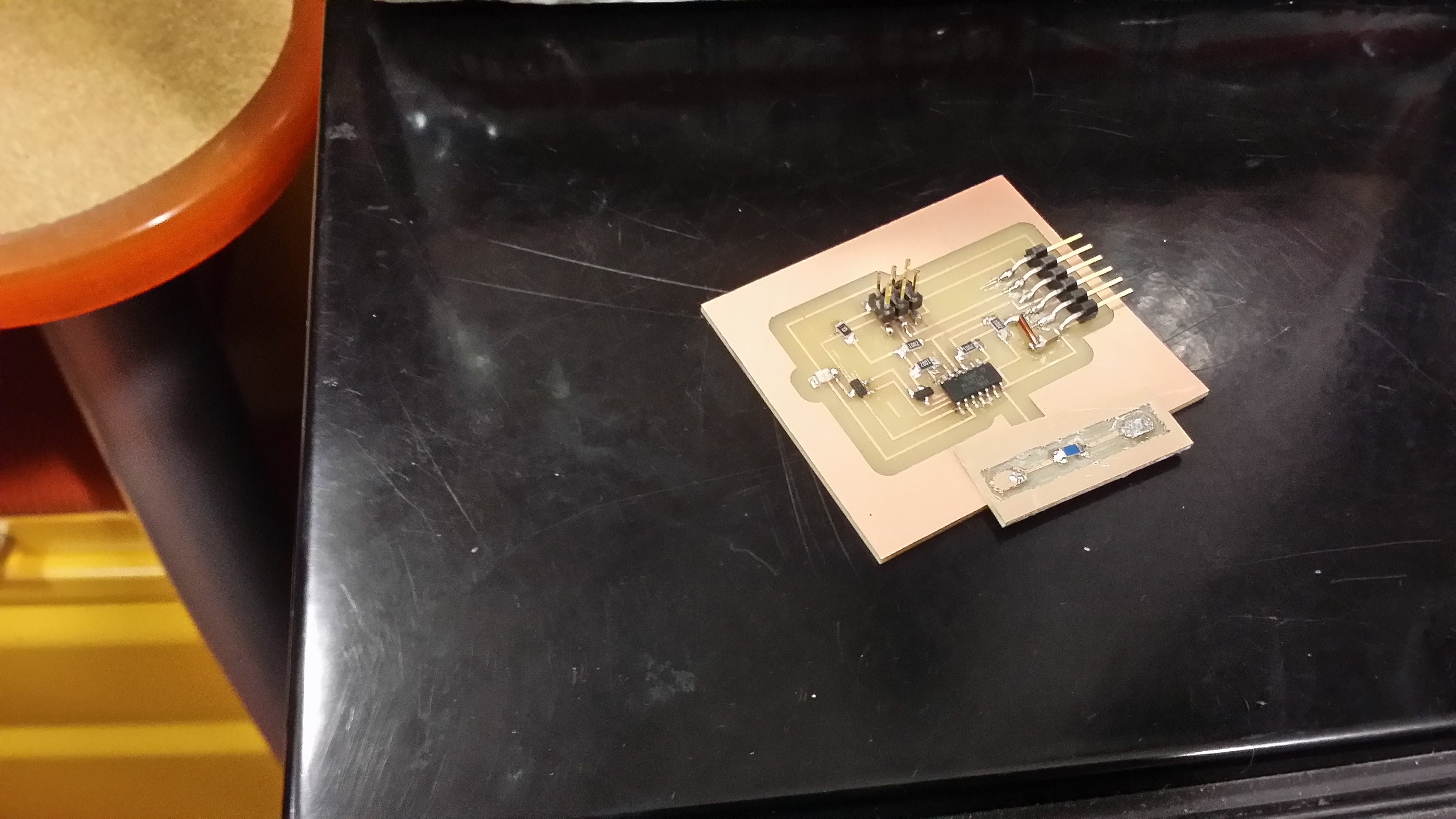
The design is straightforward - an augmentation of the original circuit. The changes are thus: 12V power comes in (and out, at one terminal), which is regulated down to 5V. The microcontroller attaches to a MOSFET that turns off when the thermristor is too hot. Otherwise, it passes through 12V from the input to the output, which will be attached as the input to the motor board. The thermirstor is put on a separate board so that it can be moved around - this is important so we can keep most of our our electronics away from our (potentially hot) heating element. The board and schematic can be found here and here respectively, and the fabrication can be seen below.
Read More / Hide
Update: Or, at least, this was the first attempt at the board. I circled back on this project, and made several more boards. In total, there were five, which you can see below.
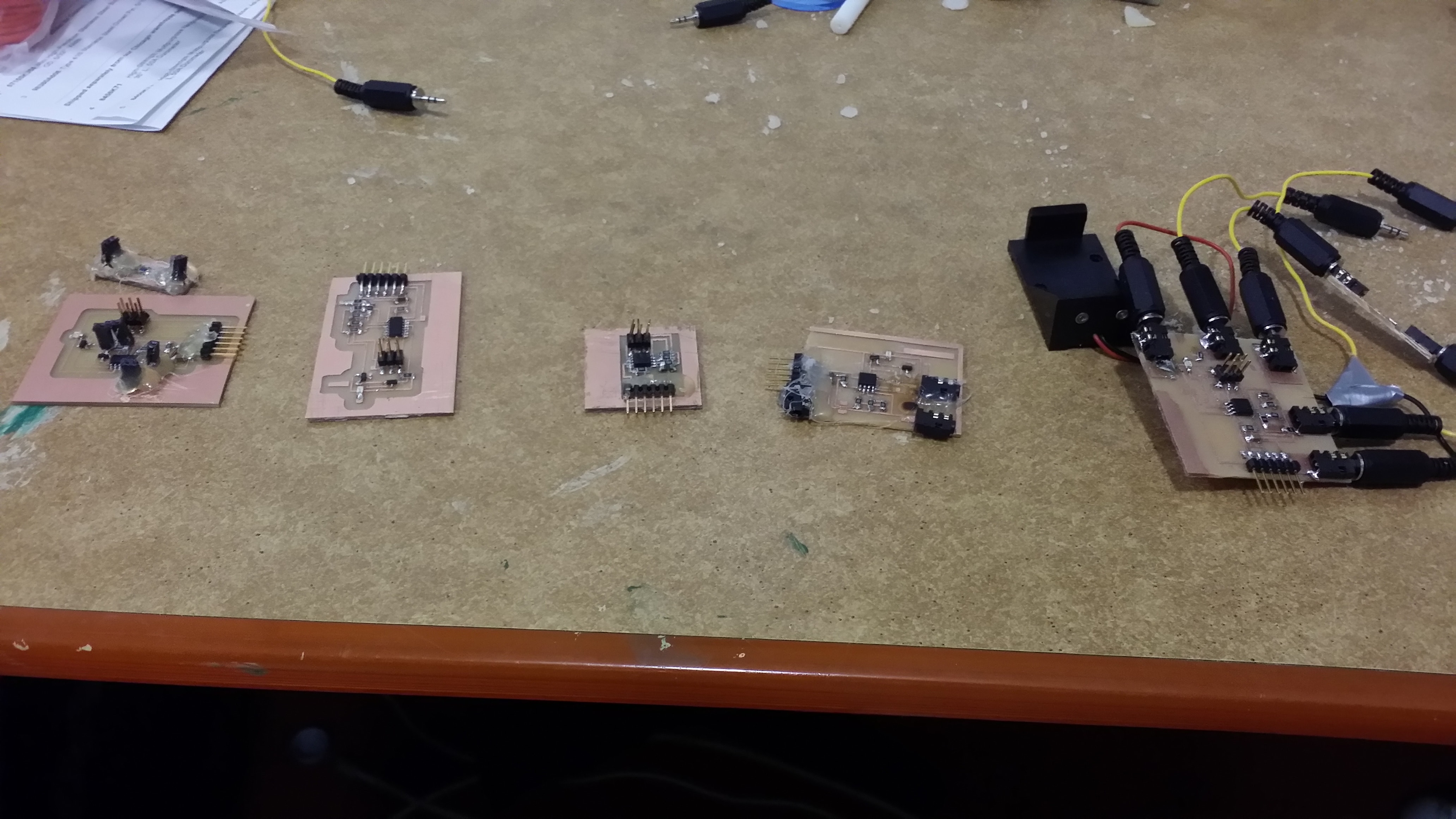
These are ordered in fabrication order. Let me go through the design decisions that affected each one.
The first board is the one described above. This is using female headers in order to separate out the boards. However, I didn't want to drill into my board as it's a rather irreversible operation, so I decided to use the SMD headers. These are very unstable when there's only a single one, and need to be held on via hot glue, which creates a mess. Further, their placement internal to the board is pretty bad, because this means that wires are protruding seemingly randomly from the board and crowding up its center. A design which places these connectors in better places is desired.
A second board decided to change the arrangement slightly in order to allow for more of the connectors to be near the edge. Unfortunately, when I got to programming this board up, I realized that the ATTiny44 had different analog reference voltage comparison setting options than the ATTiny45. Not feeling confident enough yet in my understanding of how to configure such a board with the ATTiny44's settings, I decided to switch to the ATTiny45.
In the interim, though, I wanted to get a feel for understanding the example code, understand the settings, and play around with it a bit. Here, I soldered up Neil's board (board 3)...and strangely enough, it still wasn't working! Eventually, I realized that the drawer had both RTD and NTC thermistors, and when I switched the thermistor, the board worked!
Board four, then, was my own design with the ATTiny45 swapped in for the ATTiny44. I soldered the ISP pins poorly, unfortunately, and when removing the programmer, it ripped off all the traces around those headers. on to board five!
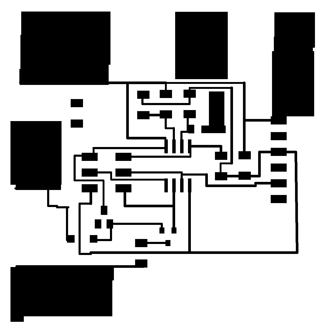
Board five is the same as board four but with more space for attaching audio jacks for power, and a few extra diodes. The fabricated board can be seen below, along with Neil's code working on it. Two of the jacks are for power, two of the jacks connect the resistor in a way that allows me to move it around, and one of the jacks is for the MOSFET controlled VCC out. The last board's traces can be seen below as well.
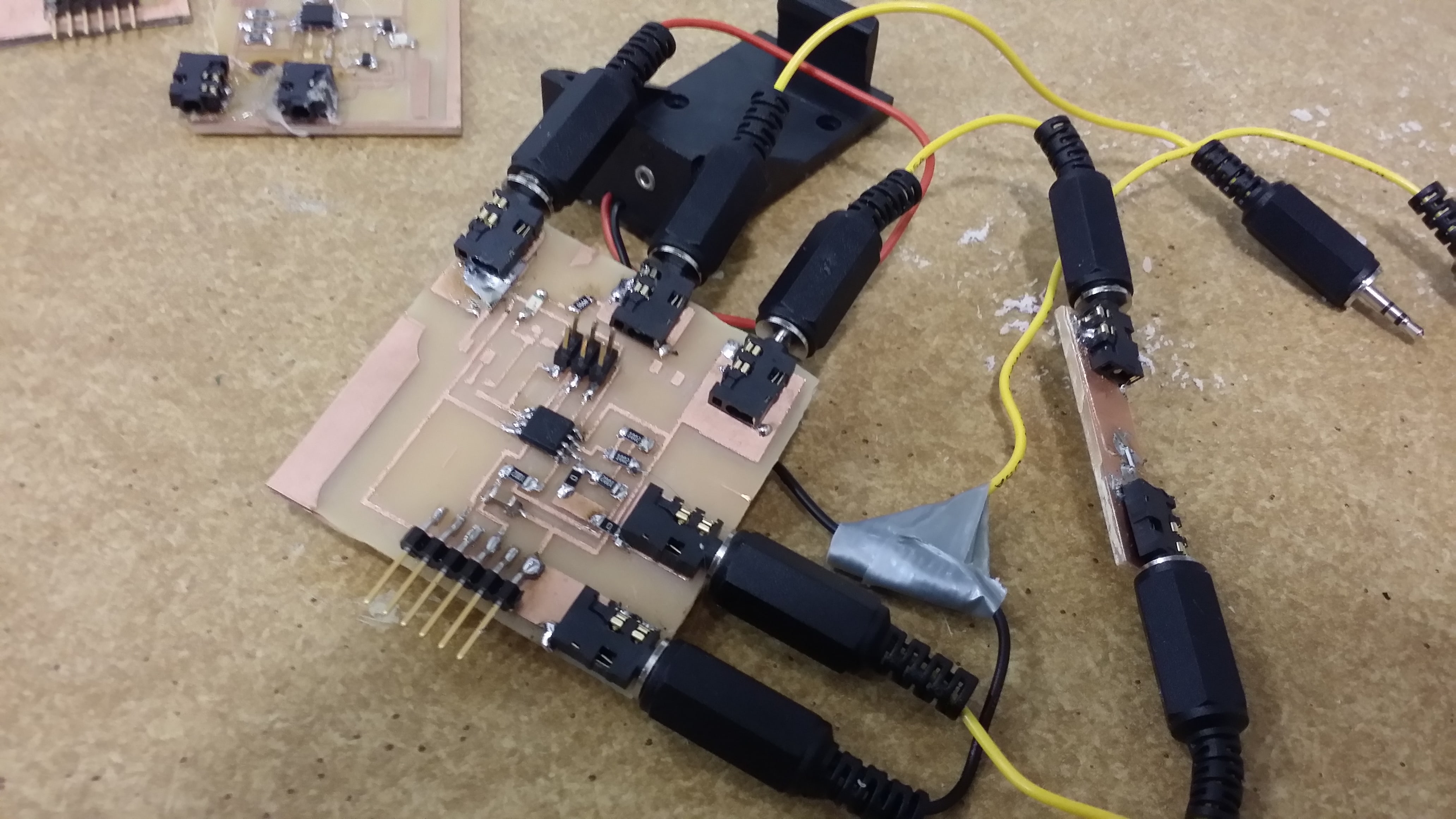
Okay, so that's great that I got the starter code working, but what do we need? First, I moved all the Python code on-board to be done in C; after all, we don't want our pen to have to be hooked up to a computer. Second, we need to make our C code work for RTD thermistors rather than NTC thermistors. The datasheet here is a huge help! We want to measure temperatures at around 160 degrees Celsius (just above the rated temperature), so we use the formula and A, B, R0 constants given on page 3. We also had to swap out the 10K resistors on our bridge to those which match the nominal temperature - for 433 Kelvin, this works out to be around 2700 Ohms, which can be approximated with two 5K resistors in parallel. I simulated this by stacking two 4.9K resistors on top of each other. In our code, we calculate the temperature given the resistance by using the quadratic equation (and taking the positive root). Code in progress can be found here.
Current Issues
Currently, the board is not working, and this has been a major bottleneck. Despite playing around a lot with the bridge resistances and the voltage gains, I cannot get the correct voltages (and hence resistances) to read off of the board when I place a 300 degree Fahrenheit soldering iron to it. I'm not sure if I'm using the wrong board settings or if I'm not using the right equation or what is happening here. Without that, we cannot control the output voltage appropriately. As one other task, I need to solder the final transistor and voltage regulator, and add a current limiting resistor so the heating element heats more slowly. One small problem with the current design is that I reversed my input and output for the transistor, so ideally that should be changed in the design rather than jumped.