Technologies Used
Python, along with SVGWrite, was used to make highly parametric, modular .
OpenSCAD was used for creating all the other shapes and adding in the propellers.
Personal Project Goals
Honestly, coming into this project, I was not too enthralled with the notion of making press-kit construction. Although it's a very powerful tool, and laser cutting (which I had some expereince with) is an excellent tool for quickly fabricating stuff, post-assembly I feel is the kiss of death for user adoption. If a user has to put something together before they can use it, they're probably not going to use it. The two exceptions to this rule, in my opijnion, are if you're appealing to members of the Maker Community who like to put things together for fun, or if you're making something as a one-off, as in, using laser cutting to make art. I don't intend to use laser cutting much in my final project, because in the space of fabricable robots, it's being (and has been) explored in parallel by some of my colleagues.
Read More / Hide
This all said, modular toys, like legos, are fun to me. And if I were going to build something, my proclivity is to build a robot. A robot will need articulation. Therefore, I aimed in this project to explore how a press-fit construction toy could be made that included articulation, including prismatic and revolute joints, in addition to fixed joints.
Oh, I also had to vinyl cut something for this project. I already had a Robotics and Automation logo on my phone, which acts as a (crappy) screen cleaner. I made a way cooler, larger, fancier, countepart logo to keep in company. Now my screen cleaner is jealous.
Methodology
I chose Python, using SVGWrite, as my main tool for drawing subshapes. I tried to make my own python library that could generate a wide variety of modules with only a few, very concise function calls. I made my design highly parametric, allowing a lot of different aspects of the design to be changed. This was for two reasons. First, it made it quick and easy to iterate on different designs. Second, it meant that by changing a few design parameters I could get a large class of different modules for fabrication.
Read More / Hide
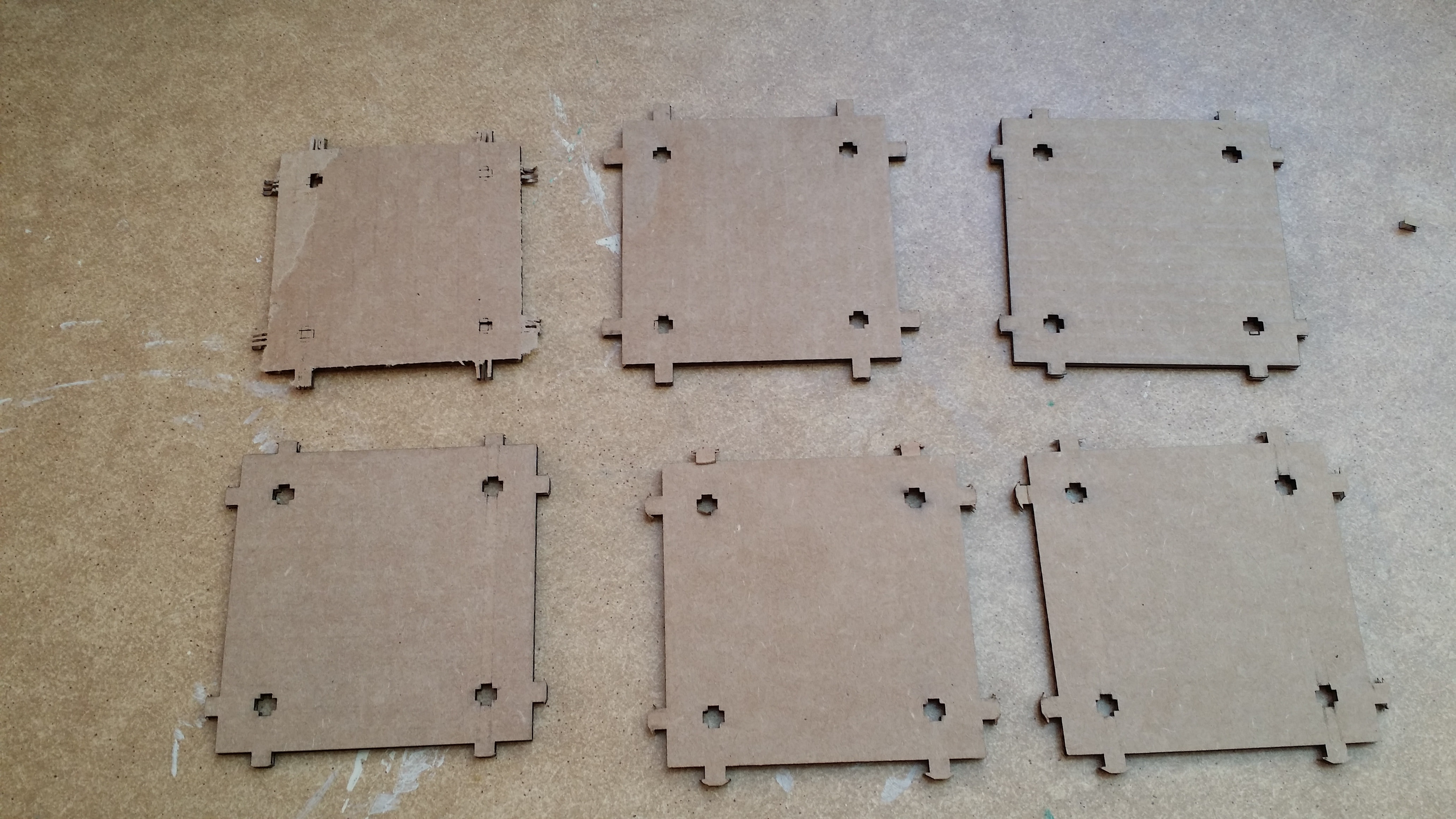
The design is relatively straightforward - there are snappable prongs and corresponding slots. Prongs fit into those slots. The slot width matches the cardboard thickness, giving a snug fit. By using chamfers, the prongs become one-use permanent fitting - they don't come out once put in. By making some of the slots wider than the cardboard thickness, I can then create prismatic and revolute joints that won't come apart.
I had had a few missteps in this project. First, I tried flexures, for improved snapability. This was a mistake with cardboard, since the corrugation pattern leads the elements to be largely unsupported. Future problems included the original prongs being too short, and having a bad chamfer angle. Fixing these two things led to good, snappable joints. These fine-tuning parameters should not be changed. However, the final suite of designs allows for the following options:
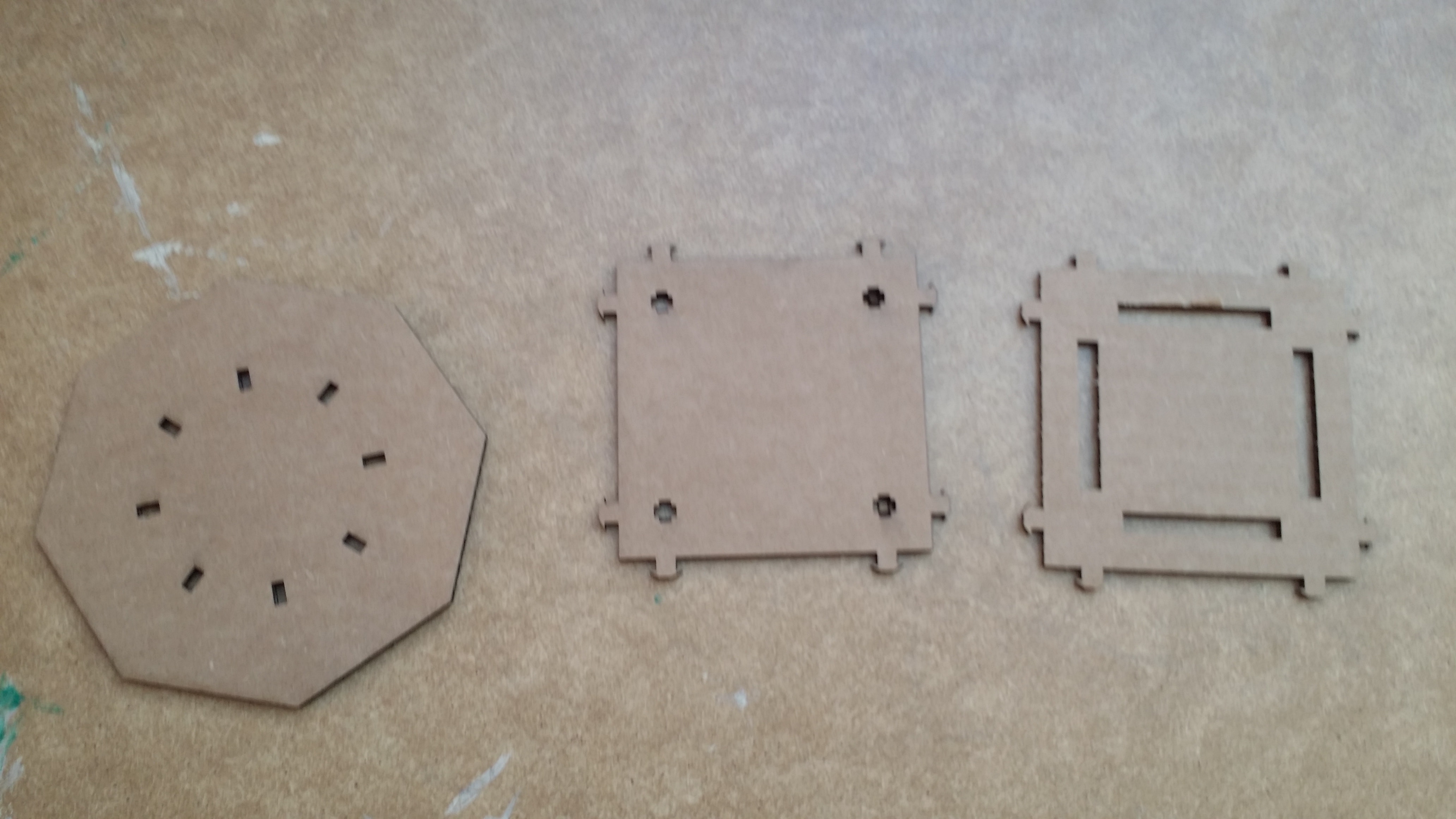
- Arbitrary regular polygon geometry for pieces.
- The option to create slots which place pieces along the diameter, in any of the diameters of the polygon.
- The option to to add prongs along all the sides of square pieces.
- The option to replace the set of slots with a set of prismatic joints.
- The option to have no slots and instead have a single revolute joint.
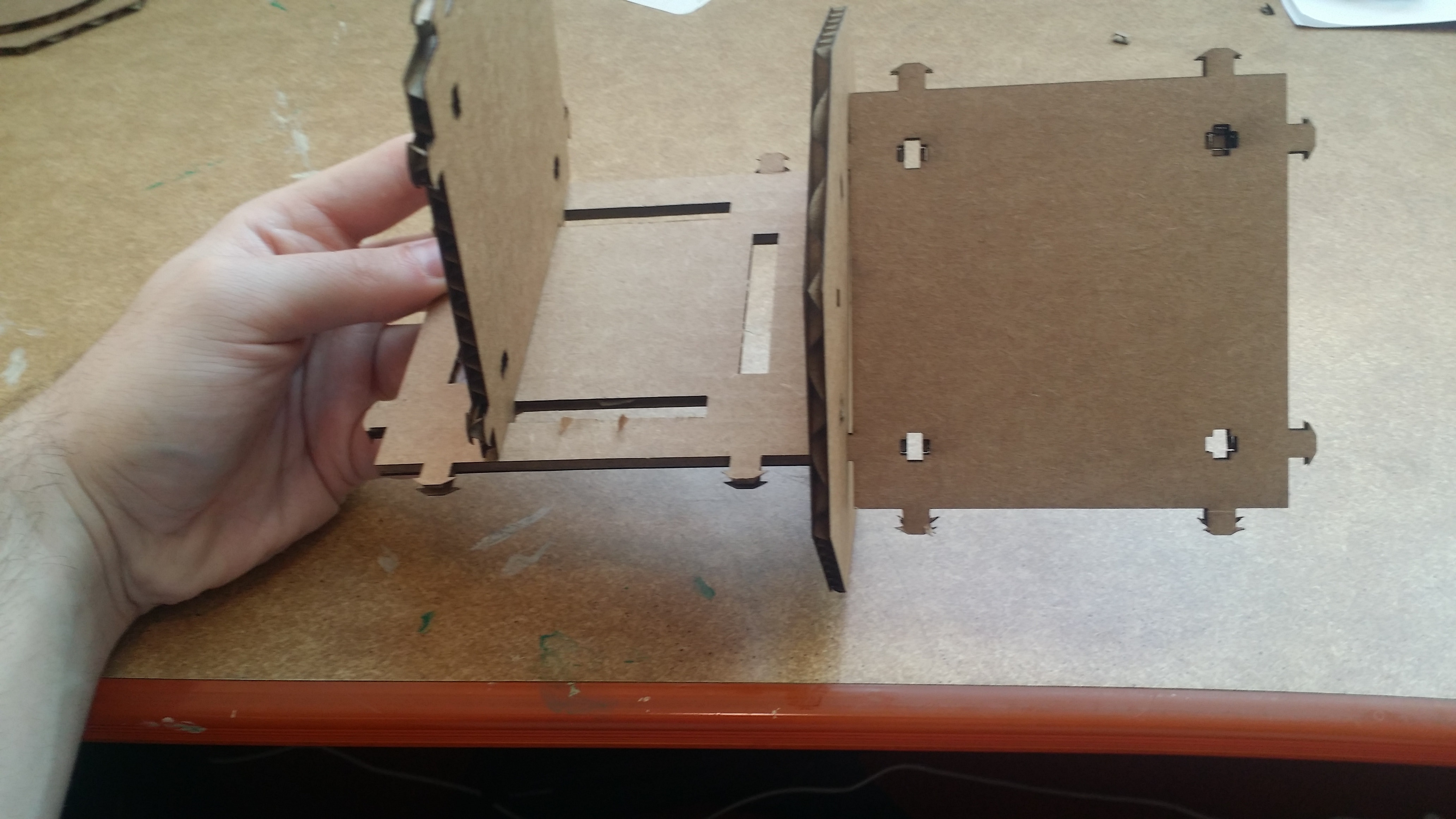
Here is an example of these pieces being constructed into...a thing. Eventually, when I fix the revolute joints (more on that next), I will use this to construct a toy robot. My little cousin has been bugging me to build him a robot ever since I told him I started working with robots. This is a start.
UPDATE: I revitted this week a few weeks later, in an attempt to update the designs ab it. First, I fixed the revolute joint. Originally, my revolute joints fabrication method didn't work. I'm too embarrassed to comment on this further. I think the below "joint" says it all.
But after playing around with the designs ab it and learning about how to make arcs properly in svg (wow, what terrible documentation), I fixed the joint to rotate approximately 180 degrees. It's not a full rotation, but it's probably the next best thing.
You can download the Python file here.
Current Issues
There two main problems with current design.
Read More / Hide
First, this robot is not going to happen. Sorry, sad but true. If I had the time to go back, I would make a key-locking mechanism for my press fit joints. The problem with the current joint is twofold. First, since the cardboard is anisotrophic, one direction of the snappable joints works well. The other direction? The prongs just completely break. One way to solve this problem might be to rotate the joints 45 degrees before laser cutting: then, given the pattern of the corrugation, one direction would have strong prongs, and the other direction would have week prongs. Another (better in my opinion) solution is to use a better building material, such as wood. But the second problem is that the hinges are rather weak in general, since the prongs are prone to break over time. The truth is I should probably build any future press-fit kits to use key-and-locking mechanisms to connect the pieces, where prongs are "threaded" through holes and then rotated into a locking configuration, rather than snappable hinges. Using simple prongs, unfortunately, just come apart too easy under gravitational torques and the stress of attachments over time.
Second, the prismatic joints are highly frictional, making them require effort to slide. Some slack room would be good, but that will add wobble, and the kerf will probably make this inconsistent. My first step will be to try adding more wiggle room, but I might need to consider additional tracks (looped back from the overhangs on the prongs, perhaps) to make them more steady in that case.