This project is a minimal USB Radio Station. It registers as a USB sound card and wirelessly transmits the audio via AM Radio plural inches through the air to a standard AM Radio! It uses no external components - just the microprocessor, a USB cable and a wire for an antenna.
The heart of the design is the Cypress PSoC 5LP. This is a combination microcontroller, PLD, and FPAA. The microcontroller is responsible for configuring the device, but does relatively little work during audio streaming. The PLD does the heavy lifting for keeping timing and shuttling data around. The FPAA creates the radio signal.
The USB Device Class Definition for Audio Devices defines how a USB device can register itself as an audio producer or consumer. There are a lot of interesting compression and interleaving options available,
This is easily the simplest of the available audio communication protocols. It is fully uncompressed raw samples delivered (on average) at exactly the rate necessary. This is perfect for dumping straight into the DAC without having to do much unpacking or thinking.
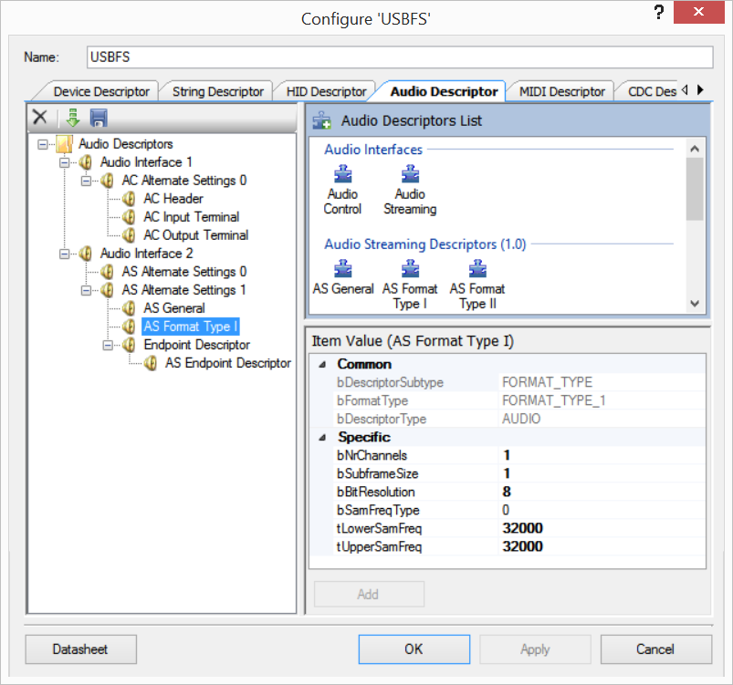
Here are the two descriptors that were most relevant for this configuration:
This describes the format type: Type 1 (uncompressed raw, no padding). "bNrChannels" is one audio channel (Mono). "bBitResolution" is 8 bits vertical (to match the DAC). The two _SamFreq parameters match, which forces 32,000 samples per second.
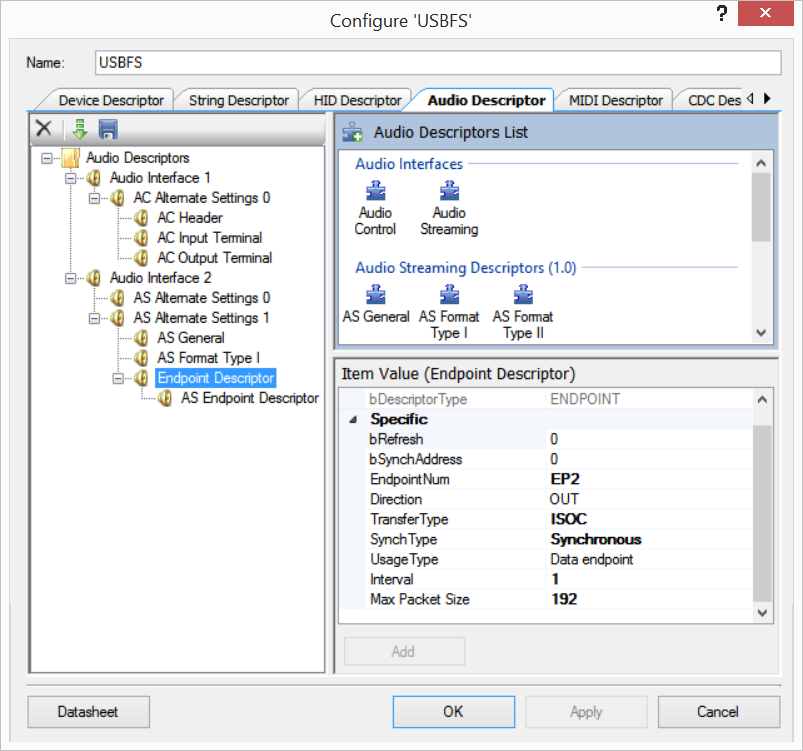
The Endpoint descriptor sets up EP2 as Isochronous . This asks for guarantees from the host on how often the transfer occurs. In turn this places hard limits on how much internal buffering needs to happen - the host promises to send at just the right rate.
The host is now sending 32,000 8 bit samples per second through the endpoint. Flowing them into the radio portion of the chip is accomplished by DMA.
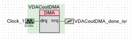
This takes the bursts of data from the endpoint and pipes them to the VDAC at the prescribed rate.
It is still possible that the device's understanding of 32kHz is different than the host's. On over-flow it drops the packet. On under-flow it will zero-order hold the last value until new data arrives. Neither are pretty, but.
The audio waveform streamed in from USB is recreated by the Voltage DAC. This signal could be sent to a headphone or an amplifier to make a simple USB Audio Card.
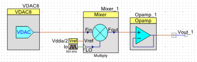
The audio is then mixed with the carrier frequency. This part is fraught with peril and detail.
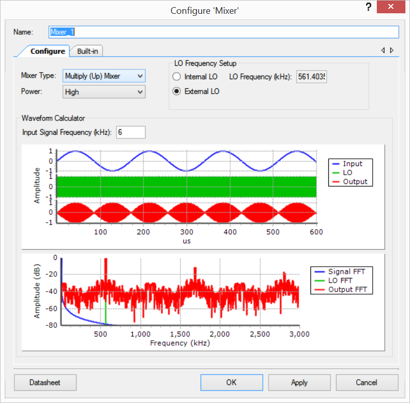
The local oscillator is configured as 560kHz. It is actually derived from the USB clock, which allows it to hit +/-0.25% accuracy without an external crystal or resonator.
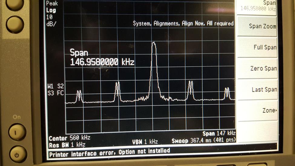
Mixing should be done with a pure sinusoid, but the up-mixer here can only use a square local oscillator. This causes the extra responses shown at 1680kHz and 2800kHz. Ideally a bandpass filter would take these out, but that would violate the "no external components" rule.
Getting the modulation index right is a bit of a hack. The VDAC is configured with a range of 0V to 1.024V, but the Mixer's reference is Vdda/2, which is 2.5ish volts. This should give a modulation index on the order of half.
Lastly, the mixed signal is buffered and sent out an op-amp capable IO pin. That pin is then fed to the "antenna".
I tested tuning by playing loud, pure tones. This made it much easier to dial in the radio.
With the radio tuned in, actual followed quickly.
I had difficulty maintaining lock between my transmitter and the purchased receiver. I had to constantly retune the radio. I thought my transmitter's local oscillator wasn't stable - I have no crystal or resonator, so it is all based on its internal oscillator. The PSoC5's internal main oscillator is 0.25% accurate when it is being used as a USB device.
Then I noticed that the tuning was extremely sensitive to how I was holding the purchased radio. I can't tell if I was pulling its oscillator, or if I was changing coupling.
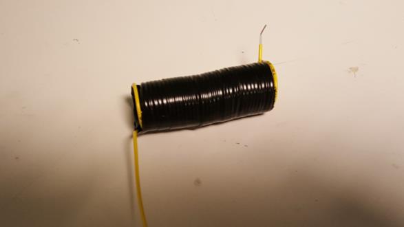
The weakest link in the system is the antenna. The super low carrier frequency means that a simple whip antenna "should" be as long as the Great Pyramids are tall. I did most of my development with an 18" long whip with no matching network.
A true matching network would require about 33mH of base load inductance. I really wanted to keep the "no external components except wire" aspect, so I made do. I made a small base load by wrapping the wire around a plastic marker ~50 times. I also extended the whip to 4'.
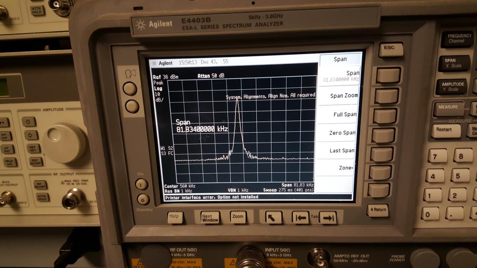
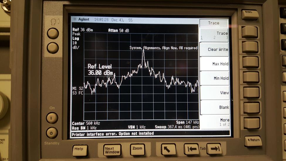
With no sound playing just the carrier is present. Reasonably clean, with most of the width coming from the analyzer's VBW.
This is from playing the pure sinewave test. The double humps on either side should be single humps, and there should only be two of them instead of four. My best guess is the square local oscillator.