For this week, I wanted to make an "analog/digital" clock - a board with two concentric circles, two each with 12 LEDs in clock hour positions, acting as a clock where one set of LEDs displayed the current hour and the other one displayed the current minutes to the nearest five-minute interval.
This requires 24 LEDs; however, the ATTiny44 chip I'd used thus far only has 8 GPIO pins. Rather than use a microcontroller with a larger number of output pins, I decided to use a technique called Charlieplexing that allows you to drive a large number of LEDs off of a relatively small number of pins. Specifically, Charlieplexing requires n pins to drive n * (n - 1) pins, which meant that in my case I was able to drive my 24 pins using 6 pins.
Charlieplexing relies on the fact that microcontroller pins are in fact tri-state: they can be input pins, output pins sending LOW, or output pins sending HIGH. By taking to GPIO pins and making one of them an output LOW pin and the other an output HIGH, while all other pins are set to be inputs, the HIGH and LOW powered pins essentially act as VCC and GND to drive the single LED that has the HIGH pin as its anode and the LOW pin as its cathode. Since LEDs only allow current flow from anode to cathode, a second LED wired up to the same two pins but reversed will not illuminate, allowing for a large combinatoric number of possible outputs.
Worth noting is that because of how charlieplexing works, it's typically said that only one LED can be illuminated at one time. While I'd imagine you might be able to get around that limitation in some circumstances with very careful planning of your pin layout (I believe two LEDs with unconnected pins, or a shared HIGH or LOW pin, should theoretically be able to be illuminated at the same time), but for my purposes it was fine to use the traditional solution to this problem, which is to switch between which LED is illuminated at a very fast rate. While this will result in LEDs appearing dimmer, since I only needed two LEDs illuminated at once that wasn't really an issue.
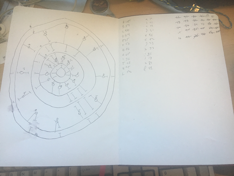
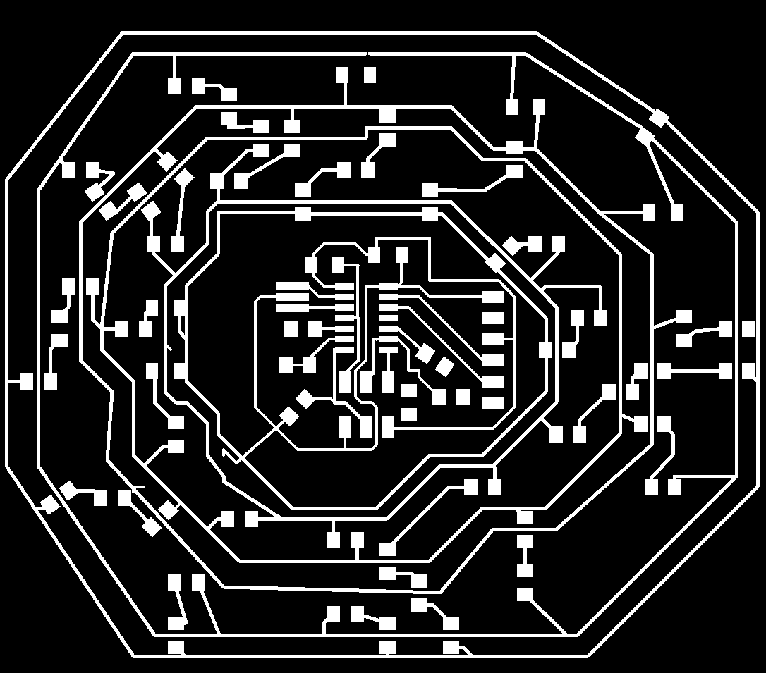
Laying out my board, requiring a lot of charlieplexing and a very specific physical arrangement of LEDs, proved very difficult. Rather than try using the Eagle autorouter to try to solve my problem, I first laid out my board by hand on paper, using a series of six concentric circles in three clusters of two as "arteries" of sorts. After working out the charlieplexing pairs that would result in the minimum number of jumpers, I laid it out in Eagle. It's likely an autorouted path might have come up with a path that required even less jumpers, but I very consciously wanted the visual aesthetic of the concentric circles to help emphasize the form of the clockface.
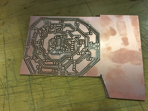
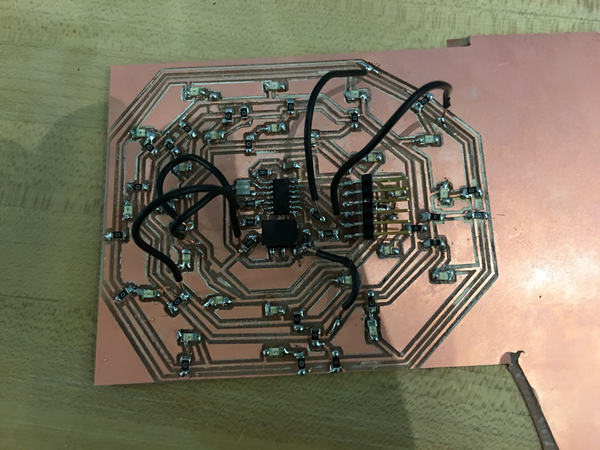
Milling and stuffing the board was a little more problematic. A number of traces ended up being too close to each other, despite passing the fab.dru design checks. There was also an issue with the Modella where the mill stopped working partway through milling the outline. I was unable, even with help, to immediately diagnose the problem, but figured for the sake of the assignment a small amount of wasteful PCB wasn't the end of the world.
In terms of softwre, the charlieplexing was fairly straightforward. I tested it out in raw C, using Neil's Charlieplexing example as a guide, as well as in Arduino, first using Alexander Brevig's Charlieplex Library for Arduino and then later rolling my own Arduino code when I realized how simple his library was.
As far as clocks go, this naturally isn't very practical. It needs to be plugged into a USB port via FTDI cable at all times, and when you plug it in it needs to have the time manually set on it. I'm also skeptical that even using an external 20Hz resonator will allow it to be a particularly accurate timepiece, but as a proof-of-concept I'm very happy with the result.