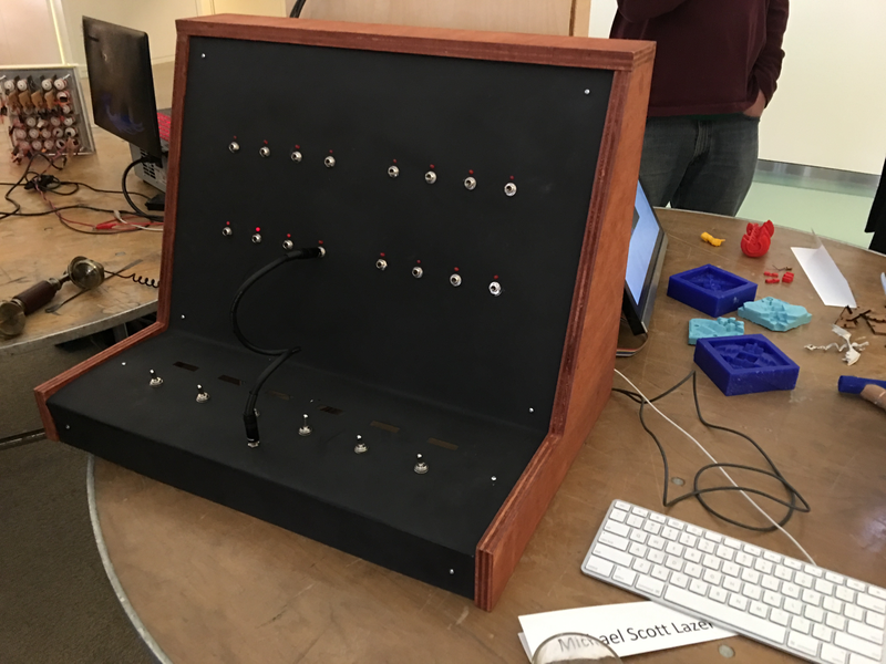
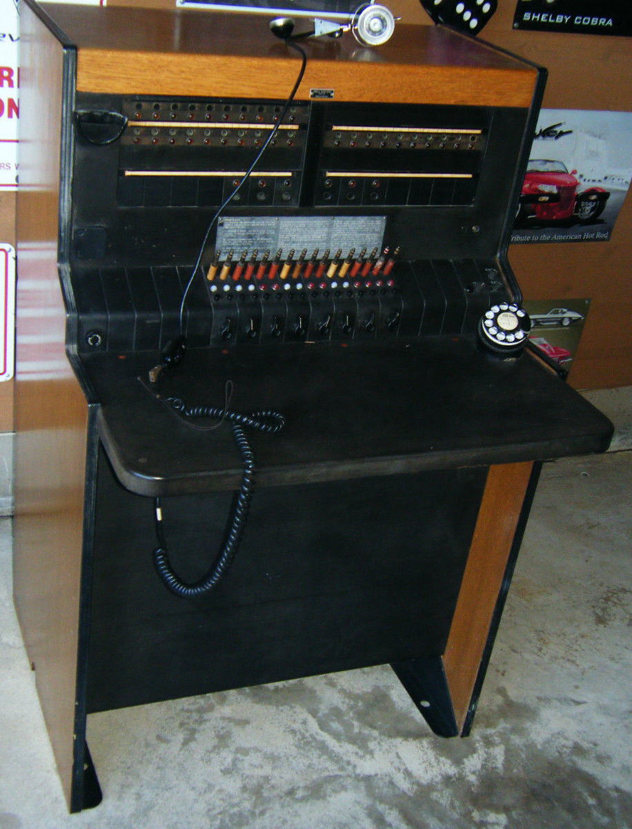
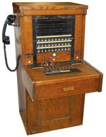
My final project idea was remarkably unchanged from my initial proposal. The idea was still to build a telephone switchboard game, in largely the same form factor. I decided to make it a tabletop unit, rather than a full standalone cabinet, modelled partly after Bell Pacific switchboards from the 1930s and 1940s and partly from vintage synthesizers like the Korg MS-20. The hope/expectation is that in the future, I will build a base unit that latches on, converting it into a standalone cabinet while still being relatively portable.

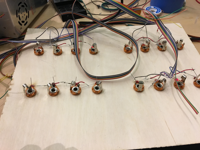
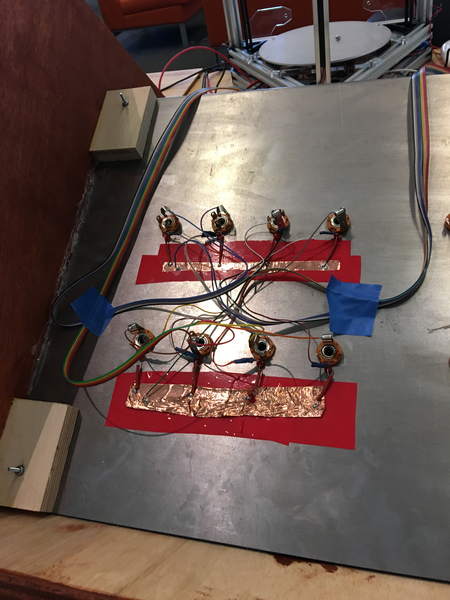
Before building the physical enclosure, I wanted to build the minimum viable version of the core game itself. I laser-cut a face plate out of wood with holes for push-through 5mm LEDs and 1/4" female plugs, and wired that up to a Raspberry Pi and an Arduino, with the plan to replace at least the Arduino (and maybe the RPi GPIO) with my own microcontroller later.
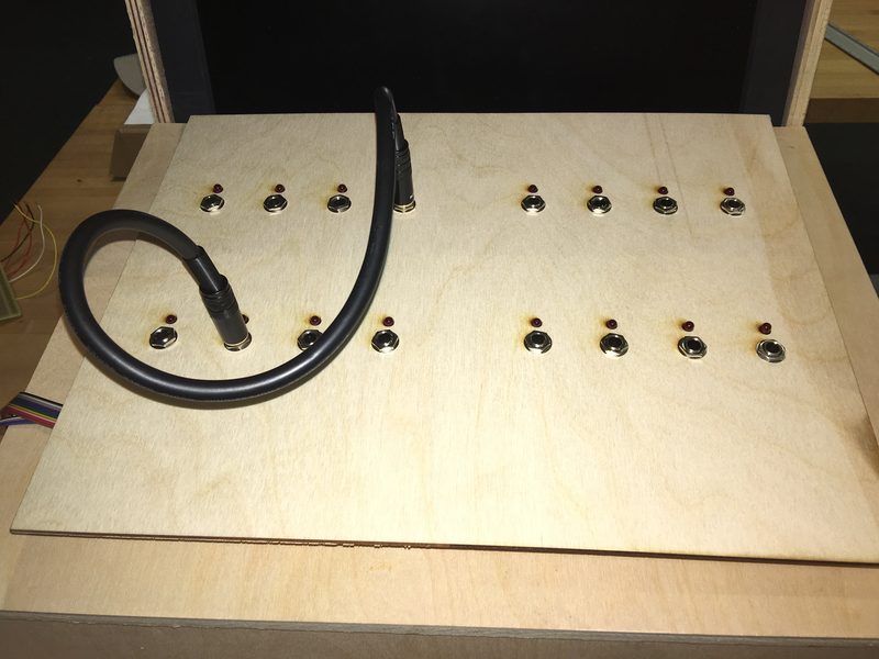
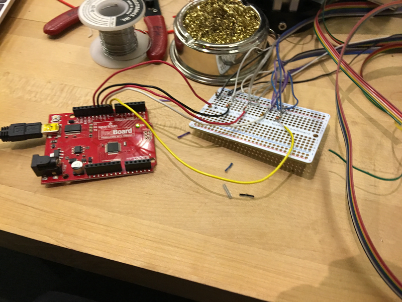
The RPi would have had enough GPIO pins for the sake of my prototype (I was only wiring up 8 of the 16 LED/plug pairs), but initially it was easier to be able to handle the software using the Arduino, rather than using the API the RPi GPIO library I use provides.
Specifically, to register input, I decided to use a pretty clever trick I found an ITP synthesizer project use. The core challenge is a fairly interesting one: given a series of ports (let's say A, B, C, and D), and the ability to connect arbitrary ports, I need to be able to figure out not just that a port is connected, but which one it's connected to. In other words, "A <-> B and C <-> D" needs to be detectable as a discrete state from "A <-> C and B <-> D".
The trick I'm using is quite simple, mostly relying on software rather than hardware. Each port is just wired up to a GPIO pin; I'm not using the ground connector in the plug at all. In my main event loop, I iterate through each pin. For each pin, I configure it to be an output and all other pins to be inputs (using the built-in pull-up resistors present in both the prototype Arduino and the ATTiny microcontrollers I've used thus far in this class), and then send a HIGH value. By checking the input value of every other pin, I can find out if that pin is being connected to any other pin.
For the sake of the game, the microcontroller code handles all of this logic, as well as tracking the state of which pins/ports are currently connected. It exposes a simple serial interface that only notifies interested parties when connections change. That is, even though it will detect that two pins are connected very frequently (twice per update loop tick, since each update loop checks every possible ordered pin pair), it will only send messages down the serial connection when a new connection is made or an exiting connection is disconnected.
That serial communication happens over JSON. The microcontroller sends messages of the format {"type": "on", "pins":[2, 5]}. This is very convenient given that my core game logic is in JavaScript; I just have the serialport library decode my serial connection as a string, and then I just run JSON.parse on that string to get an object I can manipulate directly. Is it computationally inefficient? Yes. Does that matter? Not really, in this case. This isn't a very computationally intense game, either on the host computer or microcontroller side. If latency becomes an issue, this is some low-hanging fruit to tackle.
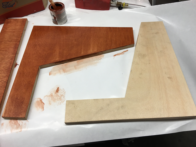
The sides of the switchboard are made of stained plywood. We picked up some nice birch at Home Depot, which was milled on the Shopbot and then sanded in quick order.
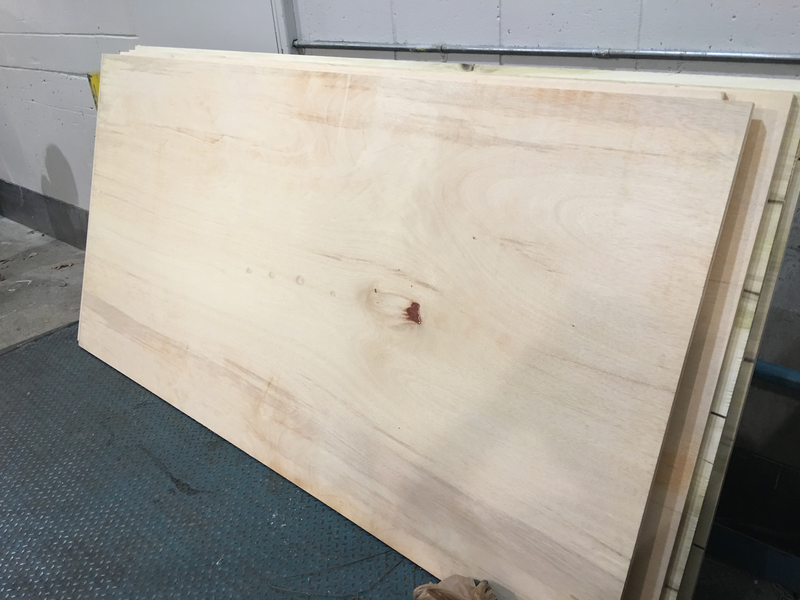
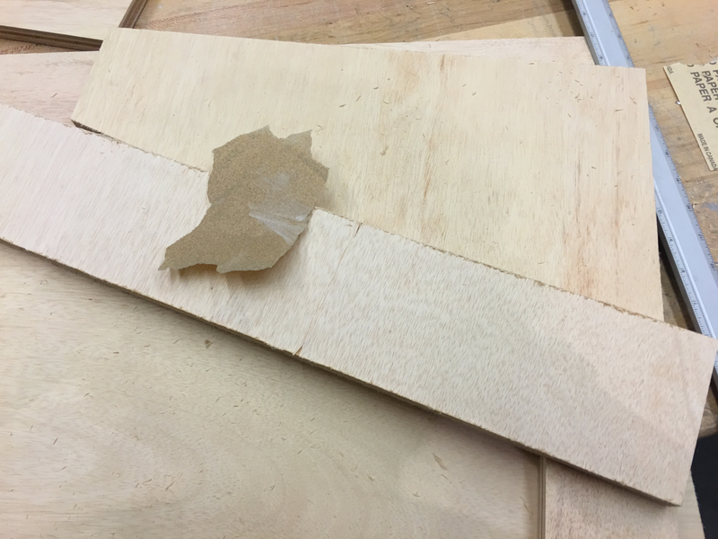
I'd never stained wood before, but it was fairly straight forward. Using a light walnut stain, I applied an even coat to all sides of the wood that would be user-facing. It was slightly tricky to do the edges without screwing up the sides!
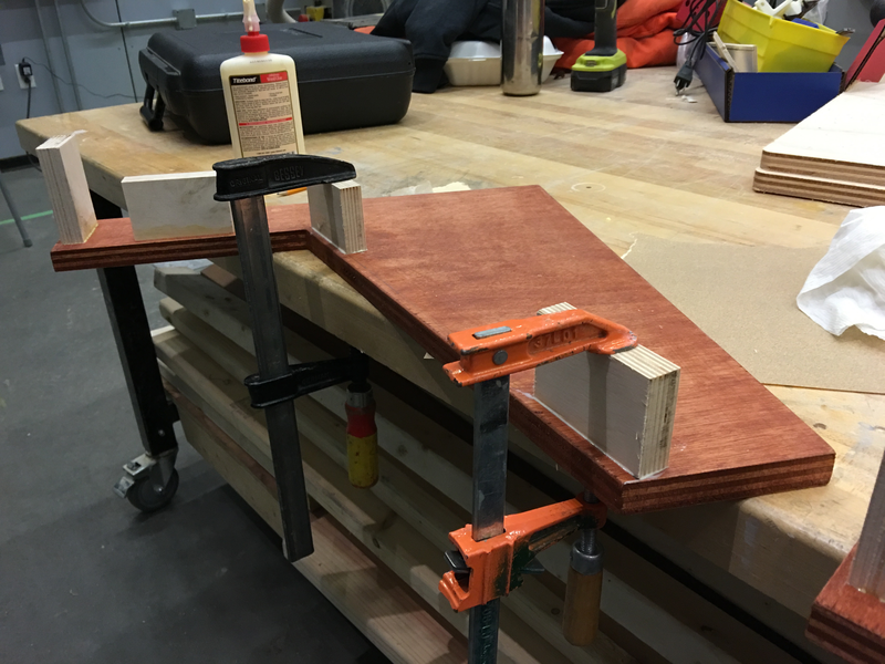
Next, I glued a few scrap pieces of plywood onto the frame to serve as screw points for the metal.
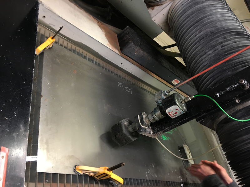
I initially assumed I'd make the main panel out of acryllic or thin plywood, but ended up making it out of steel. This meant I got to learn a whole host of new machinery!
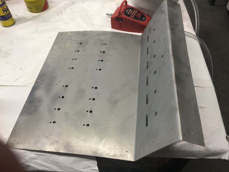
First up was the waterjet, which was used to cut a single piece of steel with holes for 1/4" jacks, LEDs, switches, and for 1/4" patch cables to stick through, plus screw holes to mount on top of the plywood. For such a dangerous and imposing machine, using it was a lot of fun!
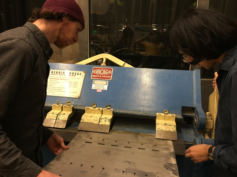
Next, we bent the steel twice. The "finger-bender" gave us a little trouble; differences in alignment on each side meant that one side of the steel had a much tighter bend than the other. Next time, I'd try to find a way to calibrate that first.
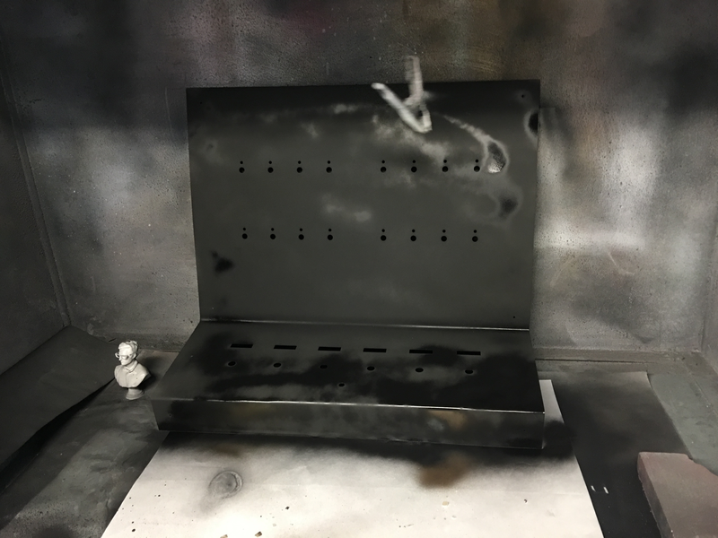
Finally, I sand-blasted and spray-painted the metal to give it a nice finish.
After screwing it into place, the main top panel bowed a little bit, which looked ugly. Fortunately, it didn't seem like it was exerting a lot of force to keep itself in position; a little bit of hot glue evened it out nicely.
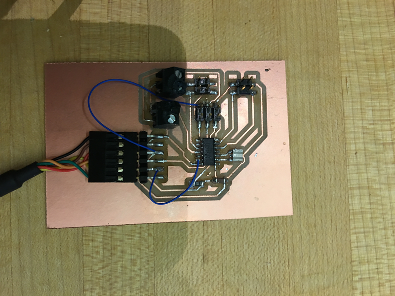
For the sake of this project, I decided to leave most of the electronics living in Raspberry Pi land, but I did want to use my own microcontroller for at least some part of it. The switches on the front of the panel seemed like a good place for this. I made a board with six inputs, one for each of the switches on the front (each of which corresponds to a patch cable). Using a FTDI connection, the board communicates over serial using a very simple API: every time you toggle a switch, it sends a string on a new line with two integers: the first represents the switch number (0-6) and the second represends whether you turned the switch on (1) or off (0).
Figuring out how to physically wire up the ports also proved a challenge in cable management. For the LEDs, which share a common pin within each row of 4 (more on that soon), I found it useful to use copper tape as a material to solder to.
My hope was to connect the LEDs using charlieplexing. To make that happen, I built a simple "shield" board of sorts; it accepts the 20-odd wires coming from the panel itself, routes them all appropriately and adds in the appropriate resistance, and just exposes the 5 pins that need to be plugged into the Raspberry Pi.
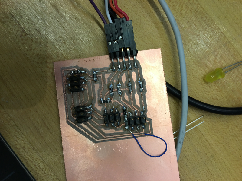
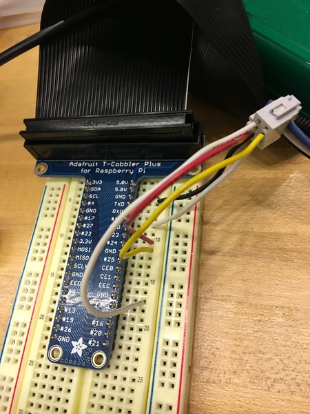
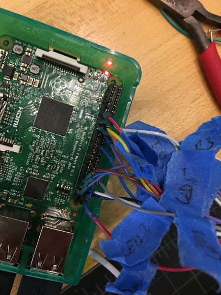
Initially, I was using a breadboard with the Adafruit breakout connector I used for the prototypes. It turned out to have some issues with shorting, though, so I switched to creating my own headers. I took two 20-pin headers and connected them together to make a header that would easily pop onto the RPi's 40-pin GPIO, and soldered each individual wire from the board into the appropriate pinhole. Using heat-shrink tubing should help minimize shorts and breakage.
The core game engine runs in JavaScript (specifically, CoffeeScript). This is so that it'll be easy for me to iterate on the core gameplay without needing the physical hardware. For example, I can run the game as-is on my iPad as a native app, using a touch interface to simulate connecting and disconnecting plugs.
The code that detects which pins are connected to each other runs as a separate JavaScript script, since the way it runs with a main event loop is a bit at odds with the architecture of the rest of the game. Node makes it trivially easy to communicate between child and parent processes if both are Node scripts, which makes that fairly easy.
Eventually, my hope is to record real audio to play to the player, but for now I'm shelling out to the espeak CLI application for real-time text-to-speech (through a faux vintage handset purchased off of Amazon).