Build an In-system programmer
Skills
Milling – input, design, process
Soldering
Surface Mount board production
Using voltmeters and troubleshooting
Background
Before this project I had no prior experience soldering circuit boards or making circuits. At the outset I understood the rudiments behind how a chip is programed to manipulate electrical signals and transmit and modify information, but I still have much to learn on that front. But truly the only experience I had making circuits and logic gates comes from Minecraft, where basic programming through “redstone” circuits is possible.
Fortunately, this project provides an easier transition into making circuits by providing possible designs upfront. I decided to stick with the design put forth in class, although I leave the door open to further variations on this design and will update this page should I complete any. In particular, I was thinking of making a 6 piece “joined” board to make a cube, so the interior environment is sealed and protected.
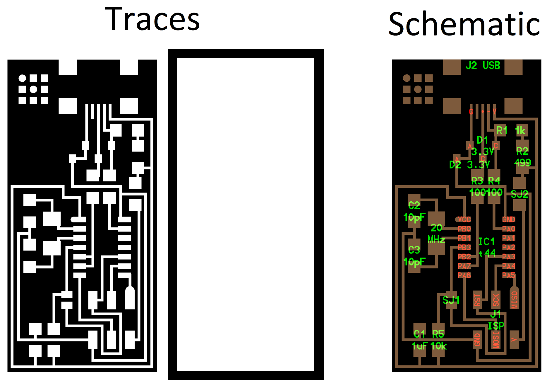
Milling
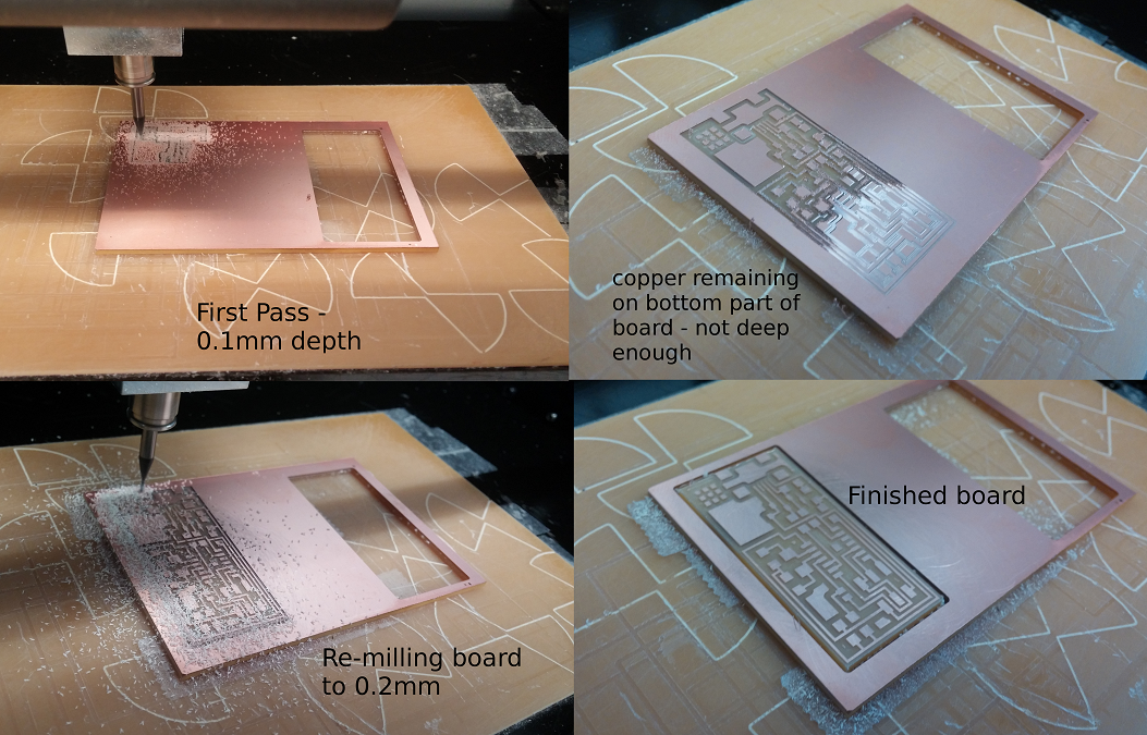
Using the fabmodules site to communicate with the MDX-20 milling machine, I uploaded the trace from the website and milled the board. On the first run through the depth was set to 0.1mm, which did not cut all the way through the copper on the bottom half of the board. Either I needed to mount to the board with greater care so it's level, or perhaps the sacrificial layer wasn't quite level anymore. Regardless, I left the board on the plate and repeated the milling process again, this time to a depth of 0.2mm, which was sufficient. I noticed many discarded boards which had this same issue, but it seems most people opted to start a new board than re-mill the same board to a different depth. This struck me as wasteful, but I might have done the same thing if Rob had not told me to re-mill the same board again. I think in my mind (and perhaps others') I didn't believe the milling machine would be precise enough to mill exactly the same path twice, but indeed I was proved wrong. It's remarkable how precise these tools are.
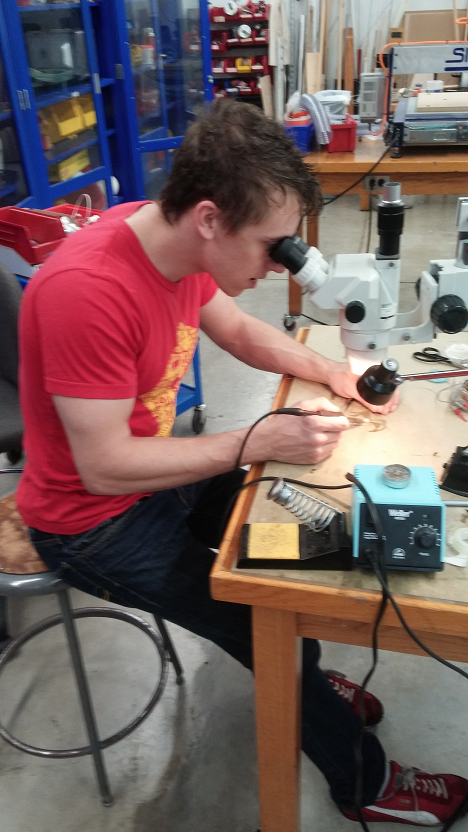
Soldering
Next came the soldering. I used double-sided tape to secure the board to the table, which stabilized the working surface. For the first board (I eventually made 2), I used the mounted magnifying lens to see the board and adjust the parts. At the end of about 90 minutes of soldering I had the board assembled, and felt that my skills improved greatly from start to finish.
The most valuable technique I found (and Neil also mentioned in class) was using the soldering tip to heat the board and the contacts before applying the solder – this caused the solder to flow cleanly onto the component while covering the pad, with a smoother and less viscous consistency than trying to apply the solder to unheated contacts.
The copper braid also required some finesse, and I discovered it worked best to lay the copper braid out flat on the solder to be removed, and then to roll the side of the soldering tip along the braid like a rolling pin, allowing it to heat while also pressing the whole braid into the solder. Using just the tip poked through the braid.
It also took practice to figure out a proper sequence for switching between holding the solder, tweezers, and soldering tip. It was easiest to secure larger components by first putting down solder on the pad, and then picking up the tweezers to align the component and then press from the top while applying the tip to the solder below. Pressing down on the component while the solder was liquid ensured the component would rest flat on the board. It was also important to keep pressing until a few seconds after the soldering tip had been removed, so that the solder would cool and you would not inadvertently move the component while pulling away the tweezers.
Programming
I followed the tutorial available on fabacademy [http://fabacademy.org/archives/content/tutorials/05_Electronics_Production/Assemble_and_Program_FabISP.html]. There was no shorting or smoking when I plugged the board into the computer, so things were looking good. The firmware file was in the right palce, and in the terminal I navigated to the folder and typed
make clean
make hex
make fuse
On the “fuse” command, the program spat an error and said there was no recognized USB device. I learned in hindsight part of the problem was that the board and the programming ISP were plugged in backwards (the ISP needed to be plugged into the Mac, which it wasn't), and also that I plugged in the 6-pin connector wires in mirroring orientations. Also, I used the firmware file from the class website, but this file would not work in the Harvard lab with the ISP we were using, and we needed to use a different folder on the desktop.
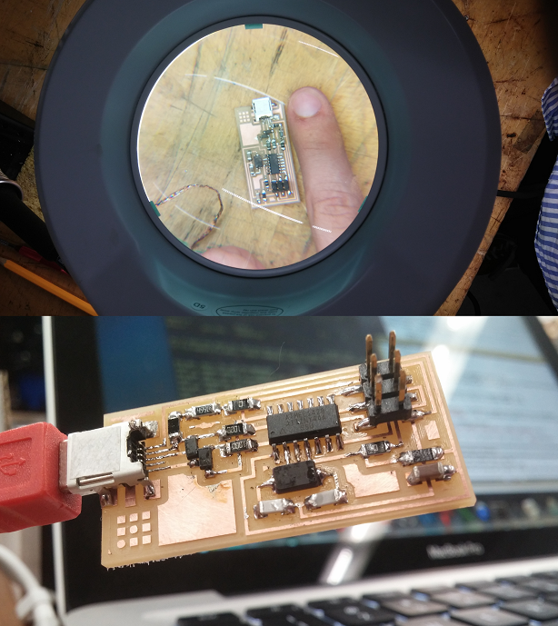
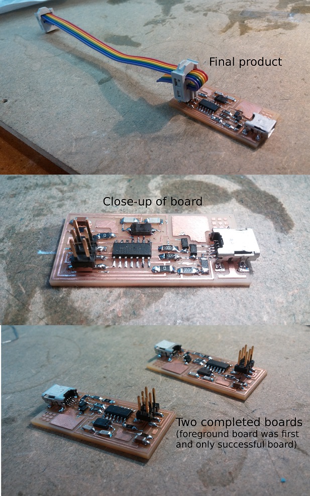
But like I said, I didn't realize any of this at the time so I ended up making a new board. I felt the board was cleaner than my first, and went together much quicker now that I had some soldering experience.
I came back the next day and encountered exactly the same issues, but fortunately Rob was there to correct my misguided ways. And lo and behold… the new board didn't work. The program indicated that the ATTiny84A micro-controller was not detected, and so there was an issue with the connections most likely. Just to give it a shot, I plugged in my first board from last night – much to my surprise, it worked! So in a sense I got this to work on the first try, and I'm not sure what that says about my perceived improvement in soldering ability…
After that, the fuse command worked, and all that was left was to type “make program”. The firmware uploaded and the board was programmed into my very own FabISP. I used the heat gun and gravity to removed the 0Ω resistors I used for the bridges, effectively locking the board from further programmatic modifications.
Concluding Thoughts
While I did end up following a procedure for building the board, I found the soldering experience very valuable, as was very satisfied with the final result. As a student at the education, I find myself reflecting on my satisfaction somewhat academically, as a signal of why project-based and hands-on learning is an effective mode of learning, especially to produce pride and satisfaction in student work.
In the future, I look forward to learning more about the logic of how these boards function, as well as how I can make my own designs for building micro-control boards which accomplish specific tasks in machines that I design.