Ideation
It took a while before I finally settled on an idea I liked – I thought about making mechanisms, or perhaps a minute fountain that could screw onto a hose or sink. I'm interested in the notion that 3D printers can be used to custom design objects which can interface with common household objects, especially though scanning. But in the end I decided that this was a good opportunity to practice my 3D modeling skills rather than 3D scanning, and so I used this as motivation to become better acquainted with Rhino and complex modeling.
I've always been fascinated by Scanning Electron Microscopy, and the images produced are breathtaking compared even to other microscope techniques. Especially the beautiful structures which can be found in nature, from butterfly wing scales to macroscopic animals and incredibly intricate structures. A classic example are diatoms – small algae that inhabit every body of water on Earth, which build beautiful and intricate silica (glass) shells. The need for nutrient and gas exchange causes these shells to be porous and highly structured for durability, but the variety of shapes and patterns is breathtaking. As a former science teacher and masters student in the Harvard Education school, I'm interested in what can be done to engage students in science and learning, and I think that a bringing the beauty of nanostructures and microworld to a human tactile level could be a valuable asset for science teachers.
Modeling
After scanning through a range of photos, I settled on this particular type of diatom. The circular shape combined with its perpendicular sinusoidal structure I thought would be a challenge to model, especially since it involves curves far beyond the capabilities of SketchUp, the only other modeling software I know relatively well.
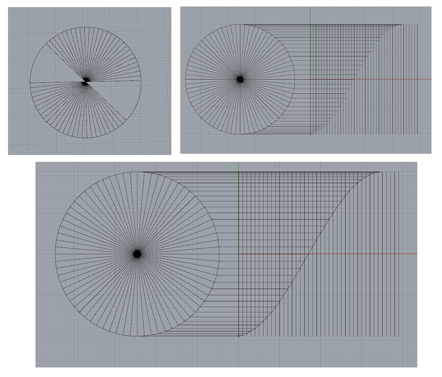
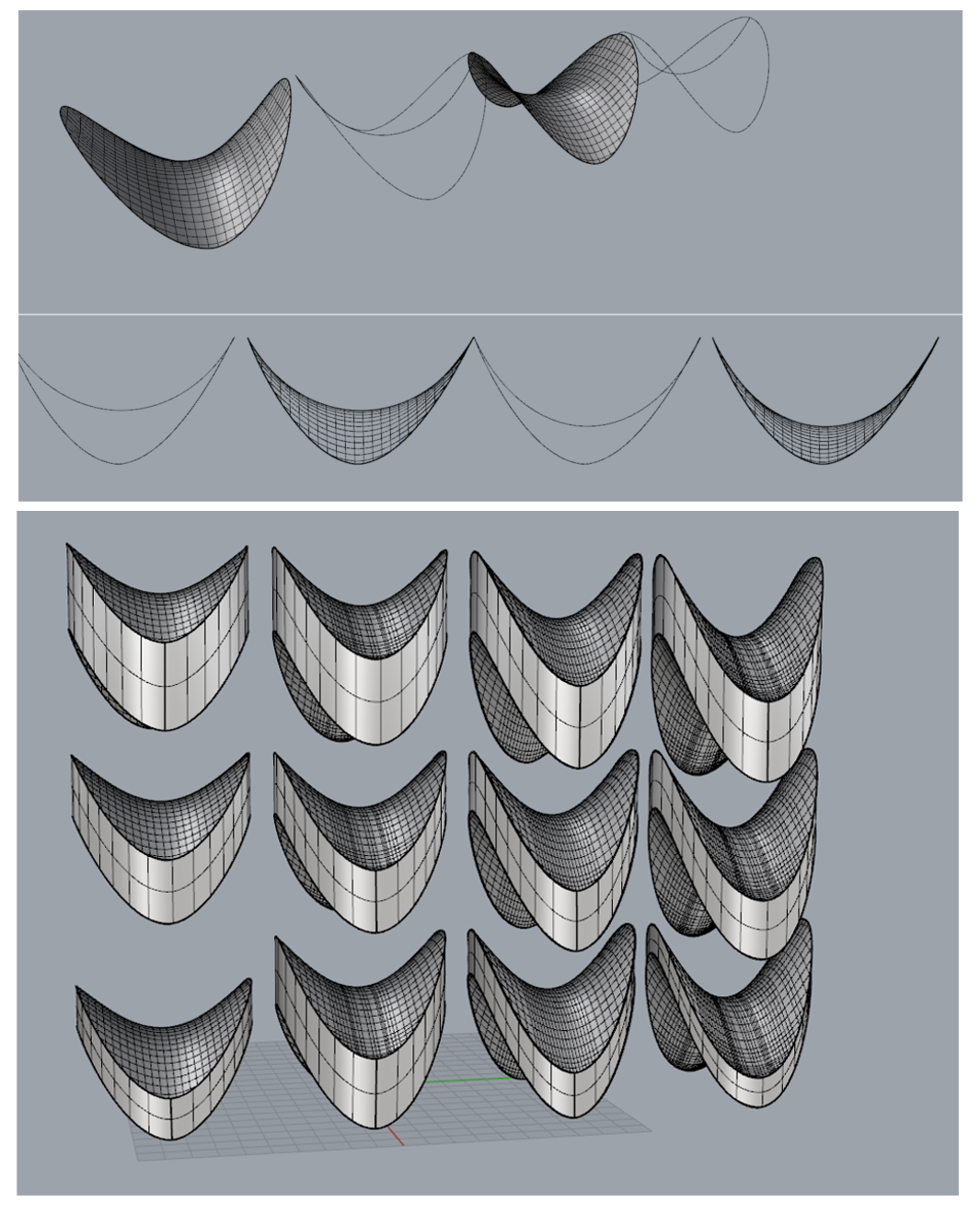
After watching about an hour of YouTube tutorials and going to Nathan's tutorial session, I felt ready to begin playing with the structure. I figured the first step would be to create the double-sinusoidal disc shape of the silica shell. So I figured I needed to start with a sine wave. I read that grasshopper might be able to do this easily, but for now I wanted to learn Rhino proper, so I dredged up some old knowledge from high school and derived a sine wave geometrically, by connecting the lines between the radii of a circle (space 5 degrees apart) and a grid. I used the curve function to connect each of the dots, and the results were quite satisfying
Next was achieving the disc shape. At first I thought I could simply use the “head on” view to align each of the control points of the sine wave with a cylinder which would match the overall dimensions of the final disc. I managed to create the curves successfully, and used the patch command to draw a smooth curving surface between the curves. But the results were unsatisfactory – because I was overlaying another circle on the sine wave in a new plane, the wave was asymmetrical, and the two halves of the diatom's shell (called frustules, for what it's worth) did not align.
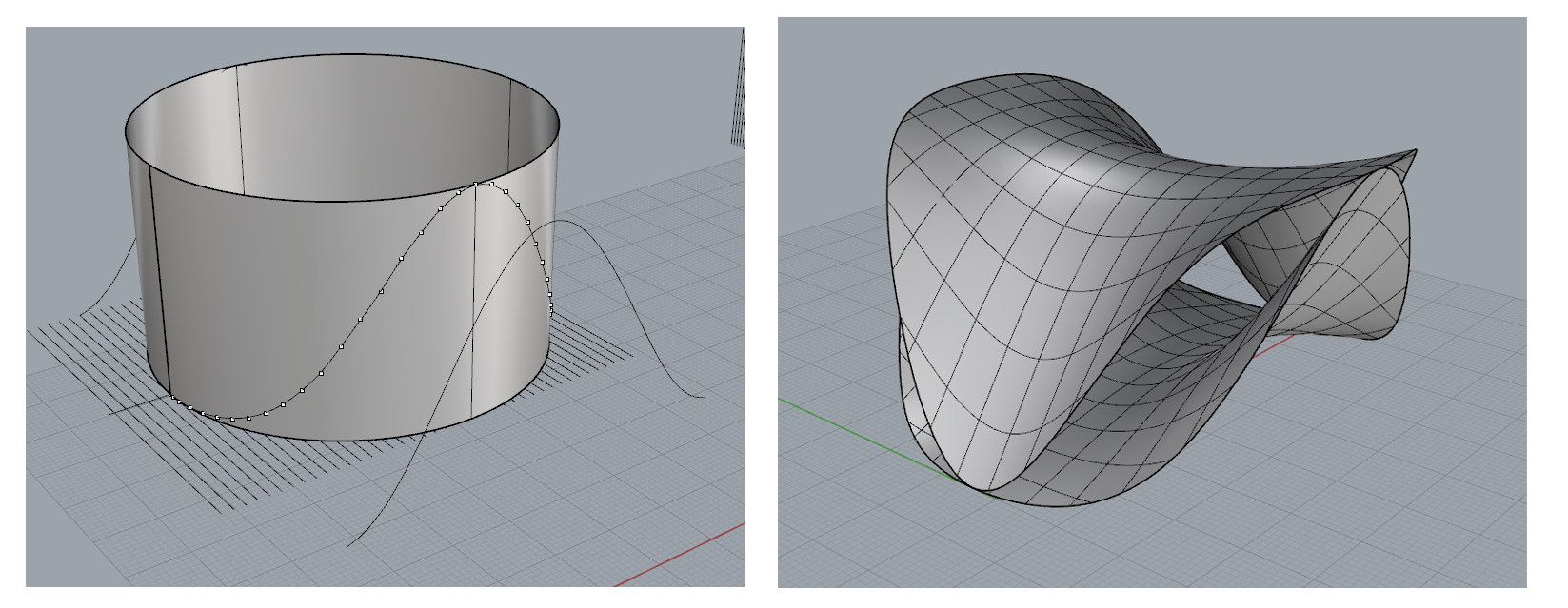
After trying a few other approached, I realized to was going to be too difficult to allign the curves manually (not to mention unsatisfying imprecise), and the cylinder was always going to distort the curves if viewed from a 2D perspective. So after minimal digging I found the FlowAlongSrf command, which could take a flat array of shapes or models and fit them to a curved surface – perfect for this application, and I would discover later this to be an extremely powerful command in Rhino. I simply flowed 2 complete sine waves onto the cylinder, and the match was perfect – far superior to my first attempt (see photo below). Once again, I used the patch command to draw the curved surfaces, which now bore a striking resemblance to Pringles chips.
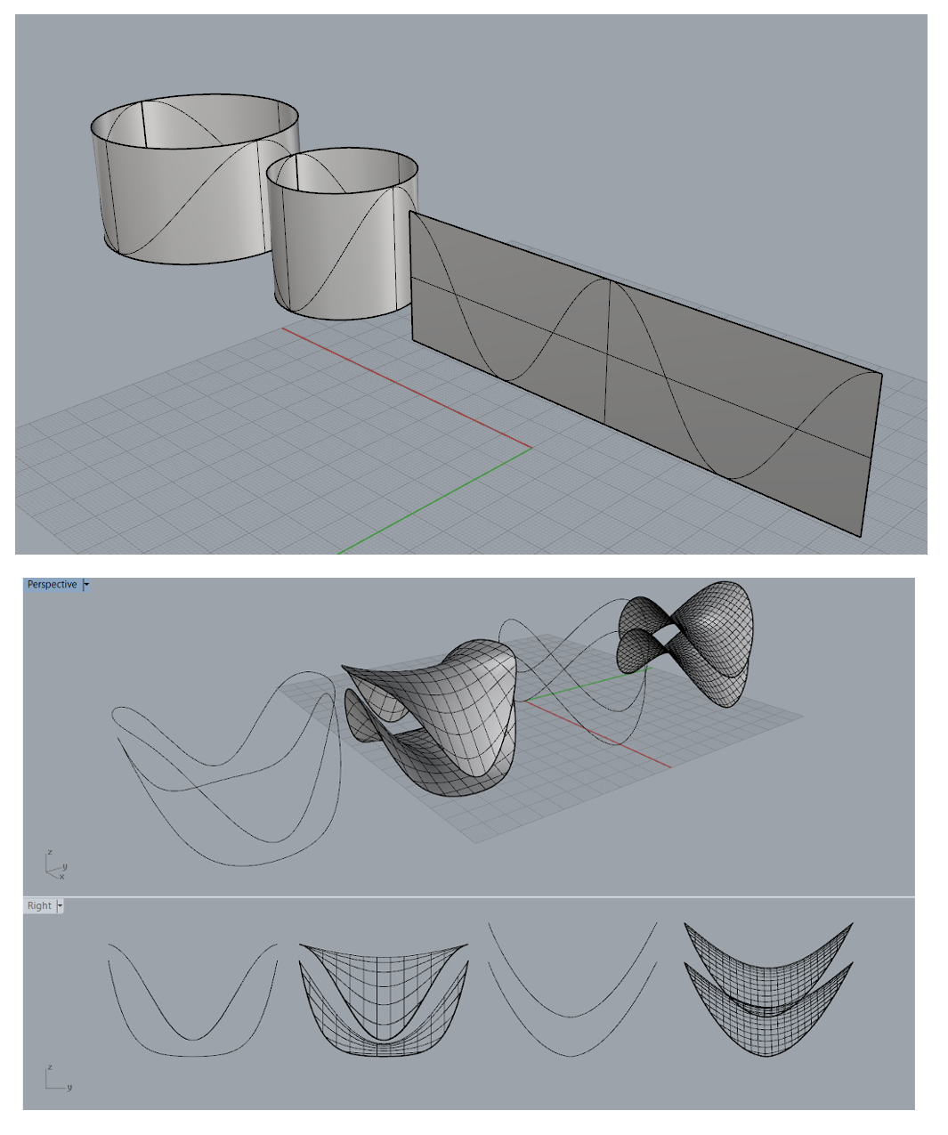
I then played with the spacing and the steepness of the curve, iterating over an array of prototypes until I found one that I thought matched best.
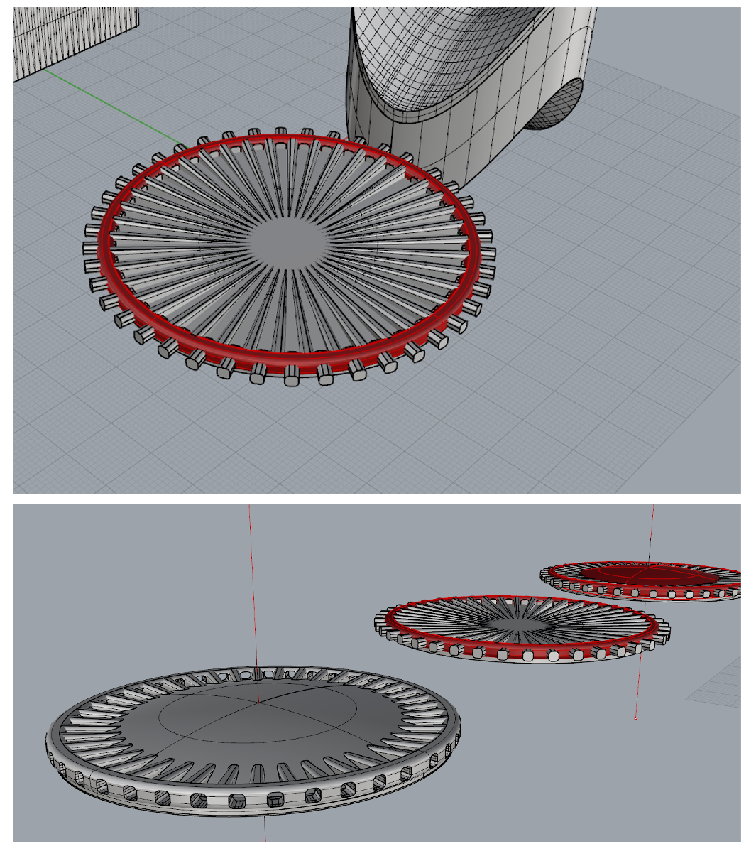
I had thought the design of the disc would be the hardest part, but adding the facets and nano-details proved very challenging. The vertical surface in the original cells are featureless, so I figured it would come down to designing a fancy “hubcap”, which I could once again use the FlowAlongSrf command to match up with the pringles chips. Coming up with a satisfying design took many hours, but eventually I created a large ring by using revolve to extrude a torus from a rounded rectangle, and then created a very broad and shallow hyperbola to make a raised dome through the center. I then arrayed a toothpaste-tube like structure around the inside of the rim to add the ribbing and troughs seen in the photograph, and then used rounded-rectangular prisms to bore out holes in the rim. The boolean commands were useful for additive and subtractive design, but no matter what I did I couldn't get the rim to join with the hub of the design, it “failed” every time. In the end it didn't matter though, because the curves were close enough for Cura to interpret it as a closed solid.
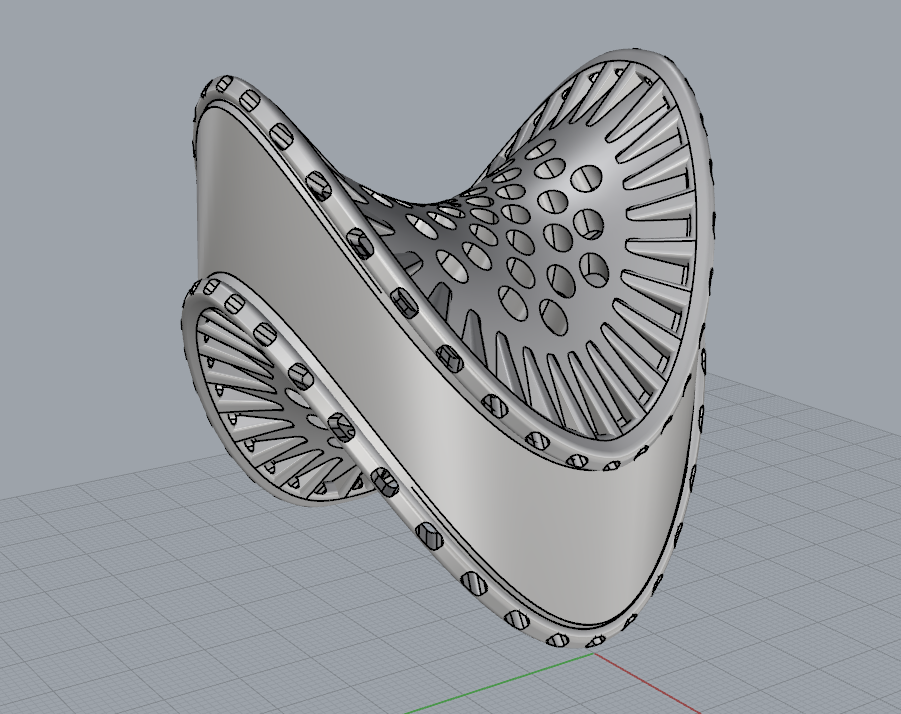
Finally I used the FlowAlongSrf command to map the hub to the frustules, and it worked surprisingly easy. However there were gaps between the frustules and the vertical wall, and so it was necessary to use the DupEdge command to extract the complex curve of the hubs, and then loft them together again for a perfect seal.
Printing
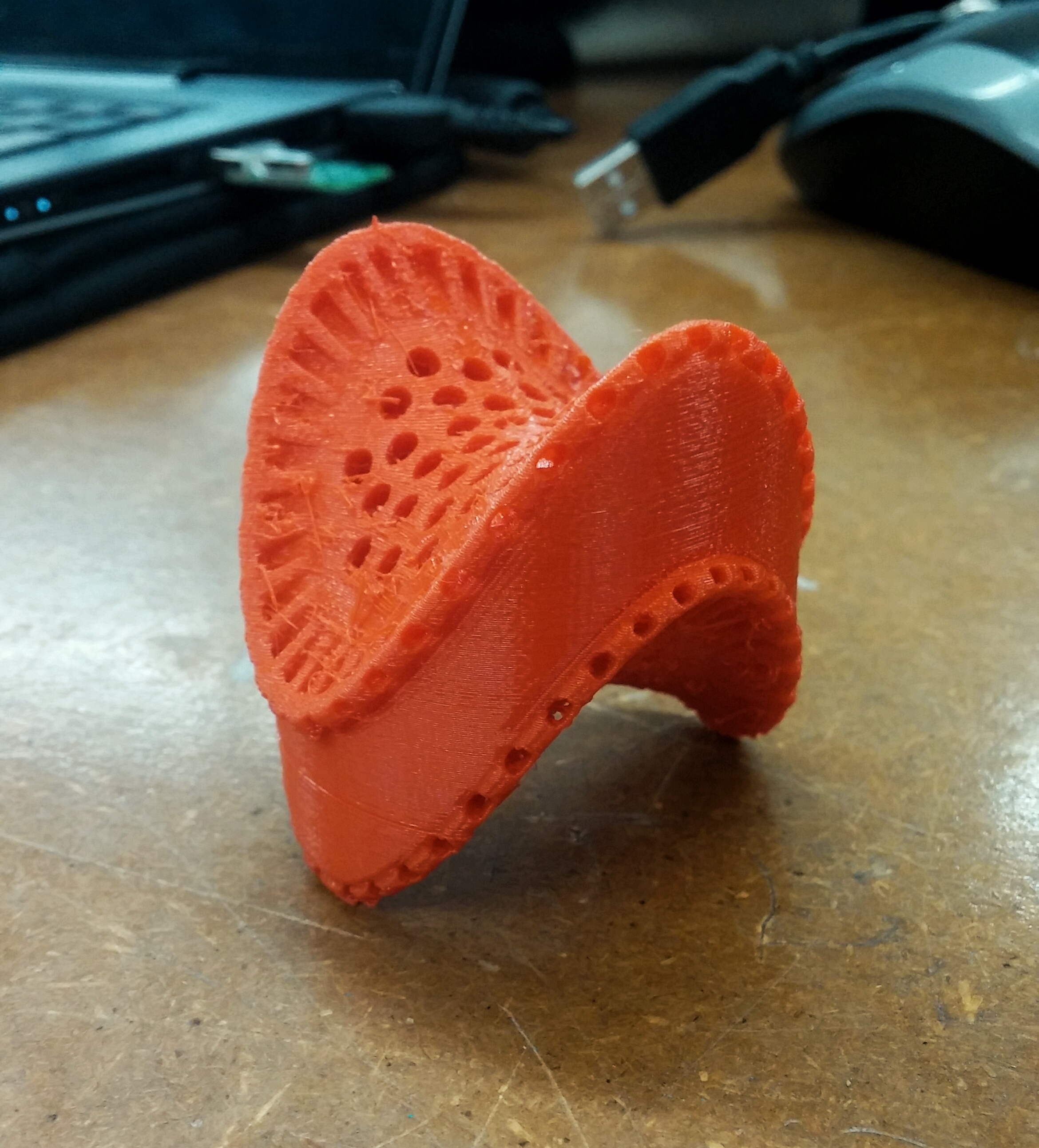
Printing was not without challenges – the geometry required a lot of support be used, and the first several attempts were unsuccessful, due to lack of initial support and also due to clogged extrusion heads. But to wasn't too long before I had my own finished model in front of me. Mission accomplished
3D Model
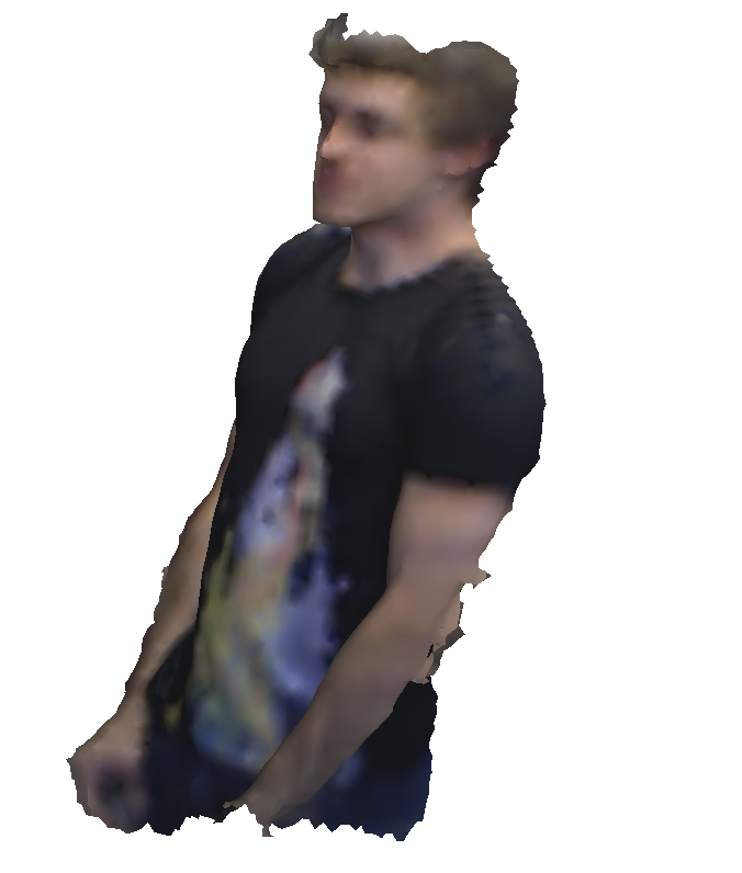
The scanner is an interesting device, and I'm certainly interested in trying a more accurate one in the future. This scan is just a place-holder for now, I want to do a more detailed body scan in the coming days so I can use the measurements to design a precisely fitting Halloween costume, as I pledged in my application to this class!