Luckily, we were given the design for circuit boards this week, though this still took a great deal of time to understand everything that was going on. I still have some work to do to understand what the exact comparative voltage should be at every point, but I'm assuming I'll gain that understanding in later weeks.
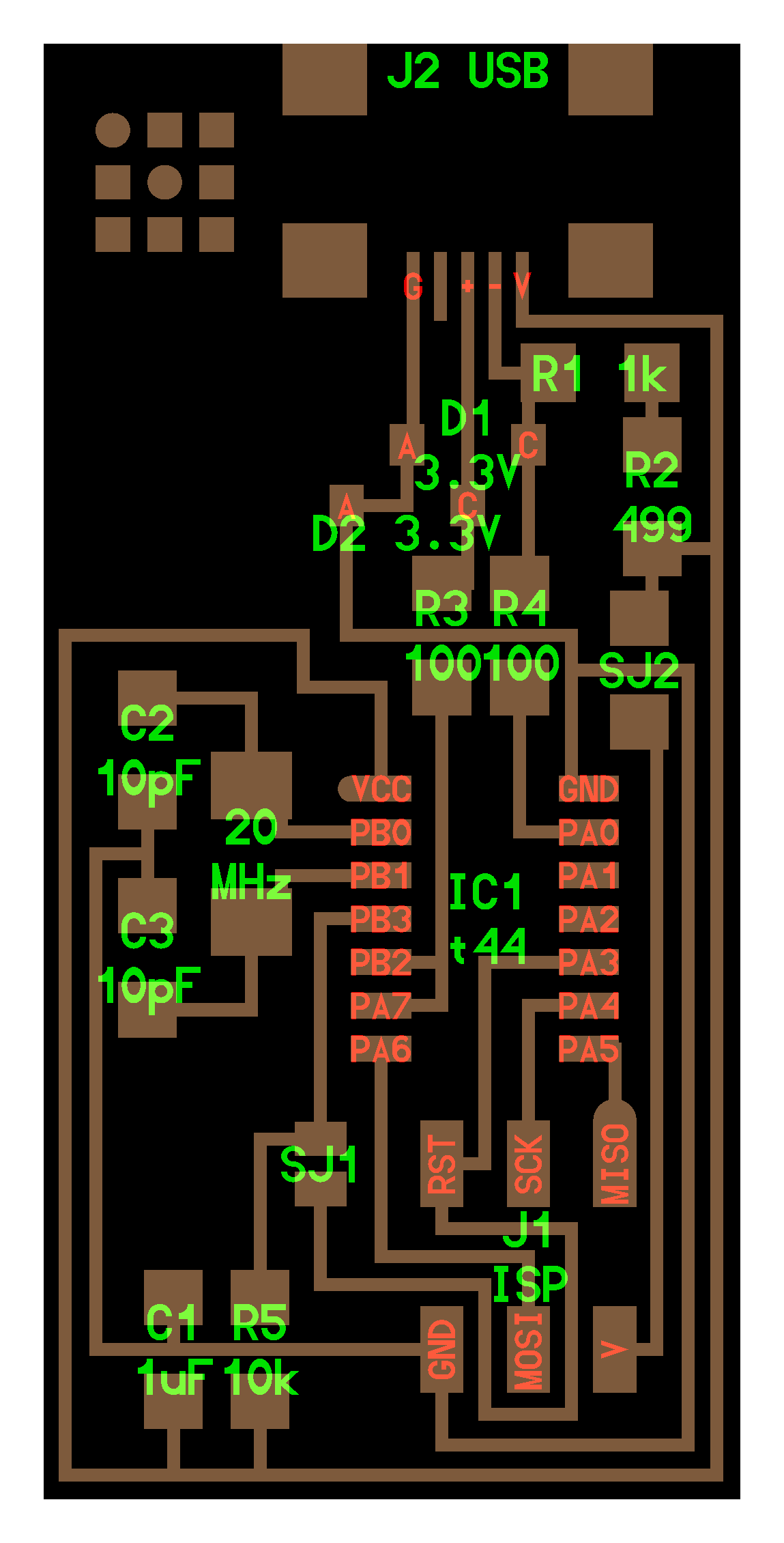
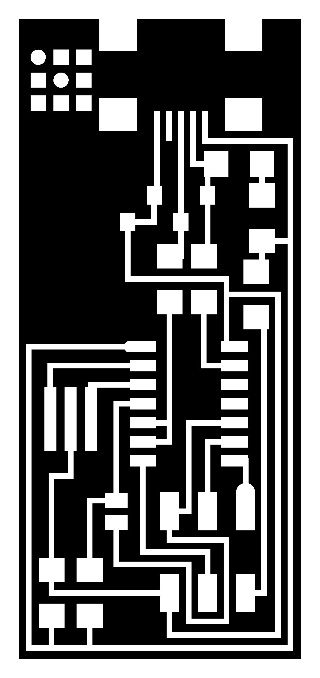
Design given for circuit and trace for milling machine
Milling proved to be harder work than I originally anticipated. Rob had a detailed list of
instructions that were quite useful and on our Roland mill. But I actually had to make 3 attempts to cut the board, since the first two did not quite cut through the copper. We finally realized that the problem was a thin layer of tape resting on the sacrificial layer, propping one side of the board slightly higher than the others. It's essential to push down all sides of the board firmly and ensure that your board is sitting on a completely smooth surface. On the third try, I finally had my finished circuit board.
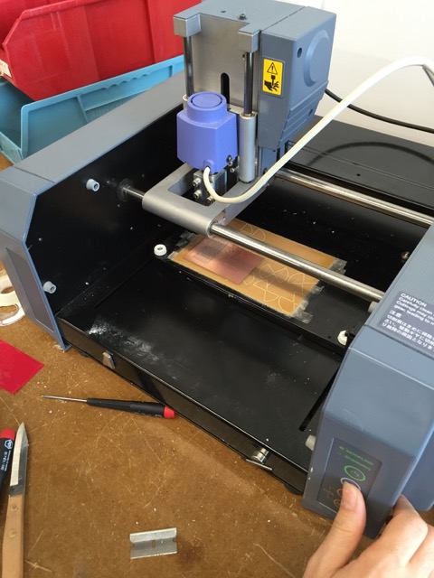
The milling machine hard at work for the second of three attempts
Once I had my board, I practiced soldering on a dummy board, and then began on mine. It took me a while to get the hang of heating up the pad before placing the solder, and on my first iteration, I had to use the hot gun to redo several pieces. When I finished the board, I tried to program it with another board already connected to a Macbook in the FabLab. The device was not initially recognized as a Tiny44 device, so I first checked to see if all the connections that were supposed to be there were with a voltmeter (they were). Nevertheless, I resoldered all the attachments on the tiny 44, and it worked the second time. However, the device was still not being recognized as a USB device after it was programmed. This time, I resoldered all the connections on the USB device, and this worked! It seems that I was conservative on the solder initially, and should use more in the future. Additionally, several of my joints wer blobby, I need to remember to heat the pad more in the future. Finally, I removed the solder bridge and the 0 ohm resistor, so my board would not reset before programming.
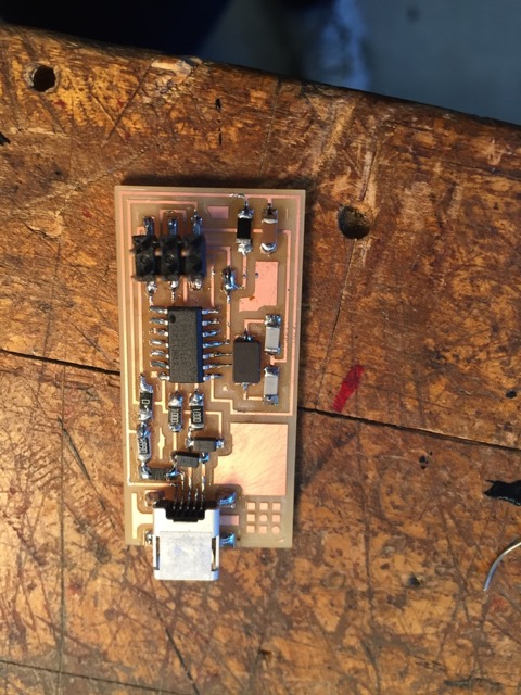
My finished circuit board, with jumpers
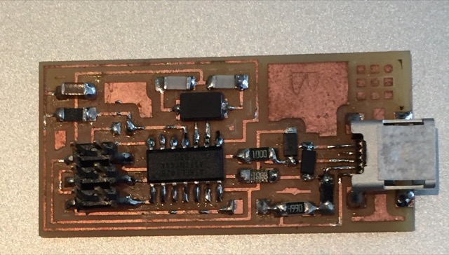
My finished circuit board, without jumpers
The final part of this assignment was making a ribbon connector. To do this, we had to feed a piece of ribbon wire into a joint and clamp it down so that contact between the wo are made. g Initially, I was using the wrong sized ribbon that Rob had salvaged, but on my second try it worked just fine.
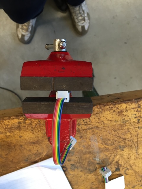
My ribbon connector being made
One useful thing to keep note of when makign a ribbon connector is that you want the clamp to clamp into place the big part of the ribbon, so the little part stays in place.
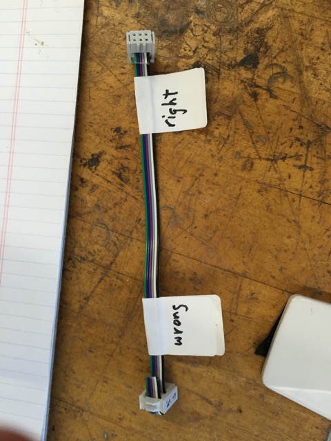
Handy guide for ribbon connector