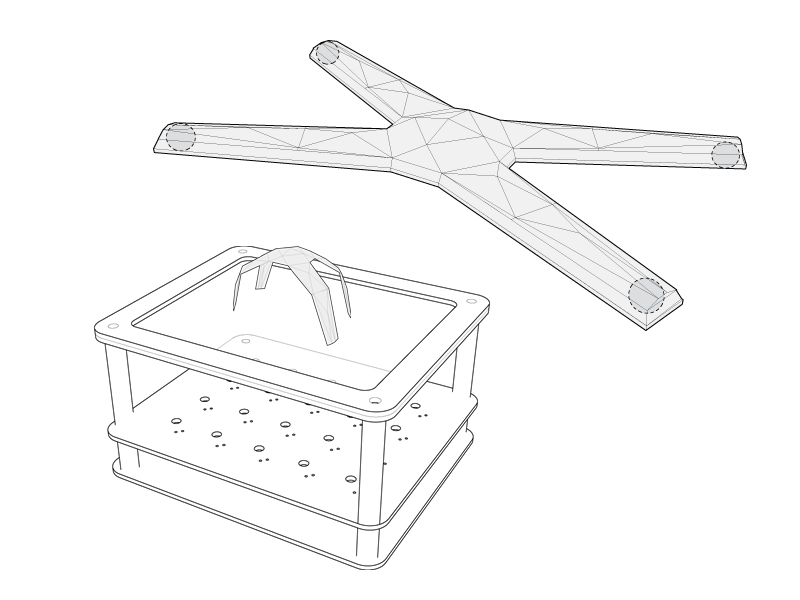
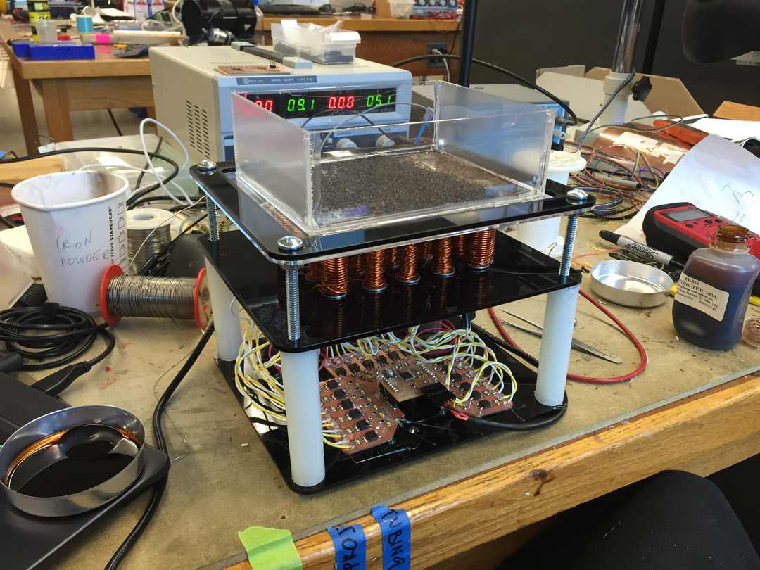
One of my first designs was a jellyfish looking "robot" that could be moved around (inspired by here & here!). The idea was to turn on and off the electromagnets to encode "simple" behavior such as rotate and go forward, back, and etc. I lasercut a chassis and 3D printed spools that would hold the electromagnets and electronics on 2 layers, and the object on the very top.
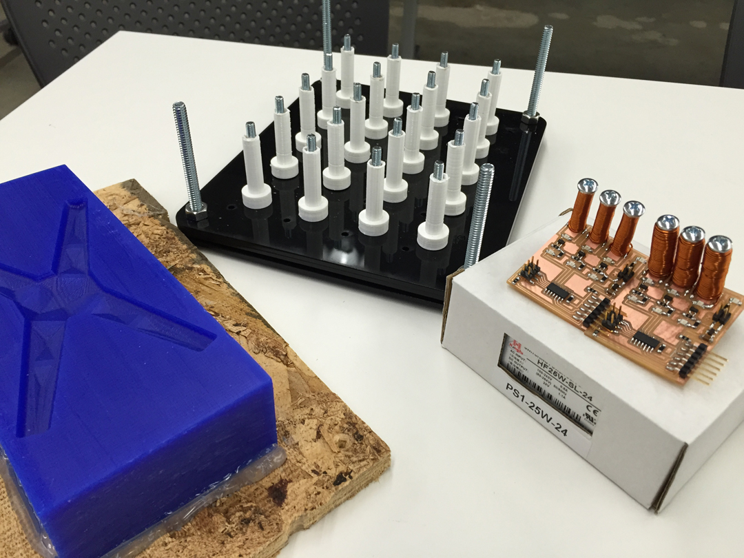
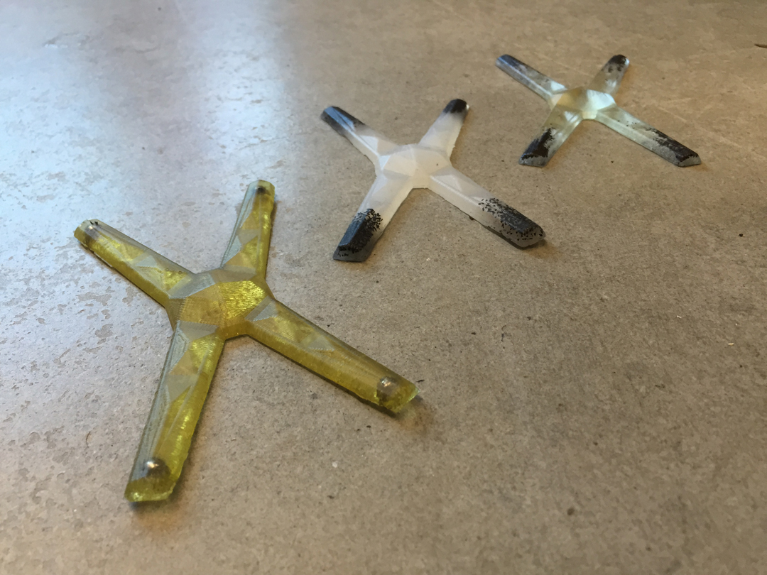
I experimented with several casts -- including Hydrospan, Mold Star 20T, and Smooth-cast 326, Econ80, Vytaflex and Reoflex. I also explored embedding magnets and iron oxide powder inside. Mixing iron powder into the rubber was fun! I think Mold Star gave me the best results because of its appearance and flexibily.
I also began making my own electromagnet circuits from the machine screws and random copper wire I found in the shop. LEDs are essential for debugging! Daniel Rosenberg from 2011 did a lot of work on electromagnets and my initial boards were based on his. Between the electromagnet and microcontroller to turn it on and off, there should be a N-channel MOSFET used... When I turned on/off the fets, it smoked and smelled of burnt silicone. Be sure to use a flyback diode to wheel the current not back through and protect the ppor little mosfets when supply is removed. This article provides a good explanation of voltage spikes across inductive loads.
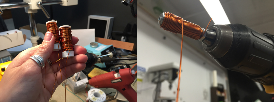
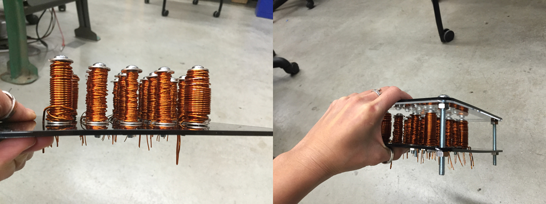
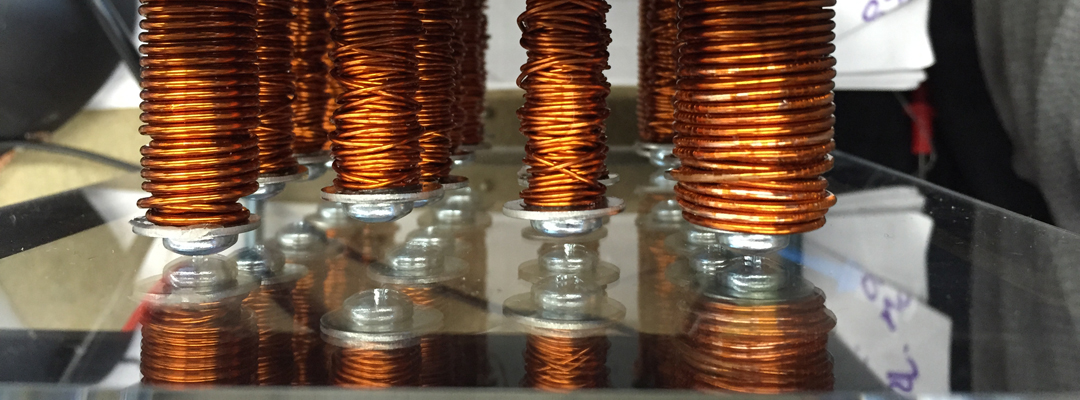
I already knew about the trick of filament winding on a power drill -- just tighten a nail in the drill with a bit of copper on it. Keeping good tension on the wire, turn on the drill to tightly wind the coils. My 3D printed spools didn't work out so well because it was a tad too loose on the screw. I also heard that there is a coil winding machine that can do this job perfectly at either MIT or Harvard...
I tested these with multiple flat layers and gauges of enameled wire. I want to use a Hall effect magnetic field sensor to quantify my findings. In general, the more windings the stronger the field. Dan Chen saw me working on several variations and told me to check if windings should be wound in the same direction; back and forth might cancel each other out. I think the common consensus across my research on this is that it's fine. Here is a calculator to estimate field strength; it uses a field value called permeability and this means you can check on various materials and choose one that gives the highest strength.
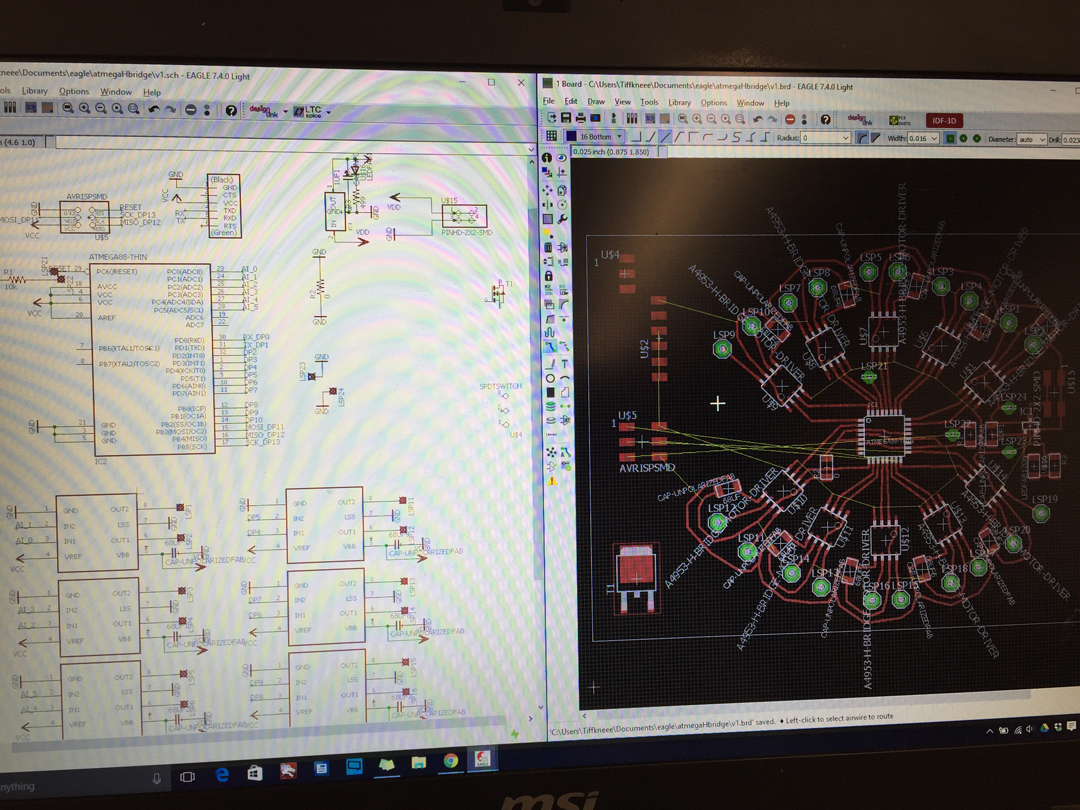
After successfully getting my small electromagnet circuits to become magnetized at my will, I became too confident and designed a big board with a lot of stuff -- like 20 electromagnets worth of stuff plus H-bridges to repel in addition to attract... Ha! I spent too many hours designing an epic PCB that I ran out of time to debug. With only a weekend left, I decided to be more modular about my workflow and revert back to what I know about attraction.
My copper collection graveyard.
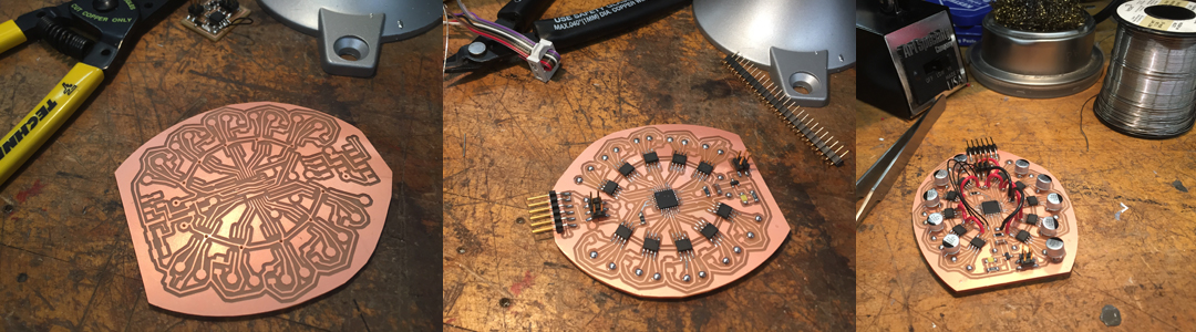
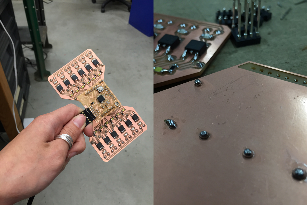
It's soo much better to do it this way -- small step iterations. I still made some mistakes, even with a more simple design, but it was much quicker to re-mill and re-stuff. The headers plug into an ATmega328P breakout board; double sided traces are most helpful for routing ground to the back and avoid jumpers, but mill off the areas where the headers touch so as to avoid shorts!
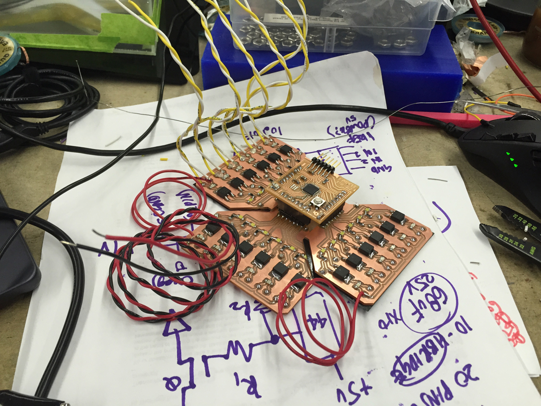
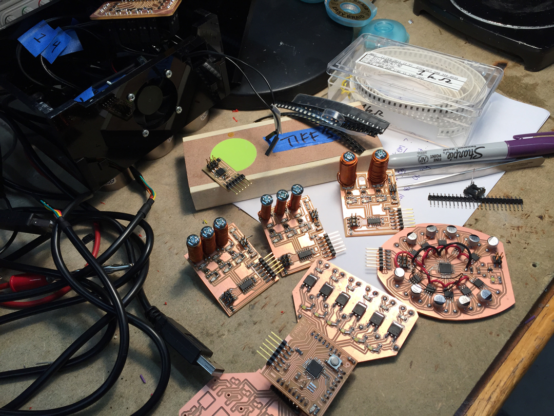
Ready to connect the copper... I also forgot to add headers for extermal power, so I just soldered some wire directly to the PCB.
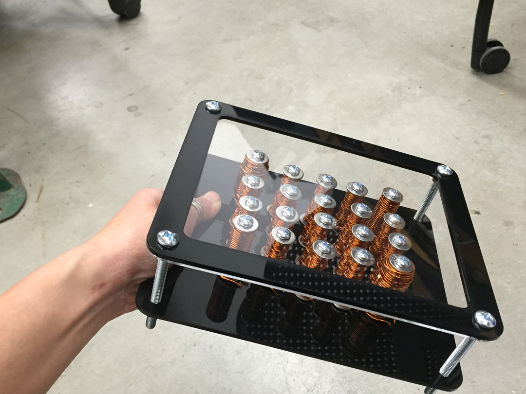
Winding all 20 coils took wayyy longer than I anticipated (do I ever learn about time management?). I also used a ton of copper (not literally) and my supply started to seemingly diminish all too suddenly -- so I scavenged Harvard's lab for all the copper I could find. I had wanted to be very methodical about the number of turns/layers, but I ended up with a wide bredth of electromagnets. I weighed them and they ranged from 20g to 80g. Oops!
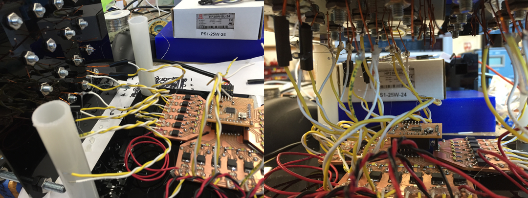
Connecting the coils to the board also took way too long. Some of my coils were thicker gauged and thus extremely stiff, while others were thin and incredibly hard to solder. I asked many people at the Science Center if I could borrow a lighter and only one person had a box of matches. Lighting the ends of magnet wire helps for attaching solder.
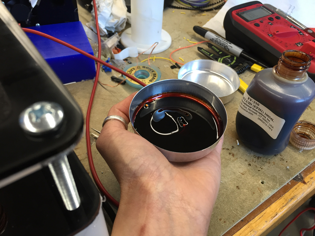
Dan from the Science Center shop gave me some ferrofluid; he said it was pretty old and may not give me dramatic spikes. I tried shaking it a bunch to re-suspend the nanoparticles.
I was surprised to learn that the magnetic field was extremely weak, but I guess my magnet wire was too thick (meaning fewer turns/layers) -- plus I ran out of material. I intend to re-build this with better coils, mounted together with less spacing in between them. I read that a shorter soft iron core may help? In any case, the machine screws in the lab is probably not ideal. I wrote a Processing interface to control the grid, but as a future project I would like to make a touchpad as input.
How to Make was hands down one of the best classes I have ever taken. I had so much fun the entire course (although by morning of final presentation I kind of hated magnets) and am super stoked to explore further some of the things I touched during class. This was almost the ultimate learning experience for me. Thank you Neil, Rob, Nadya, Dan, and all the Harvard TAs for an amazing semester!