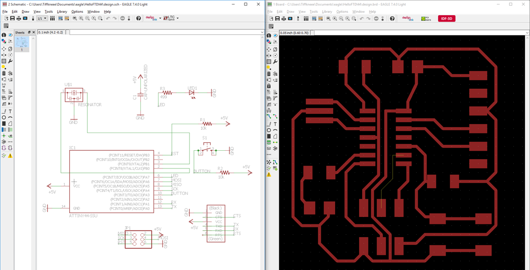
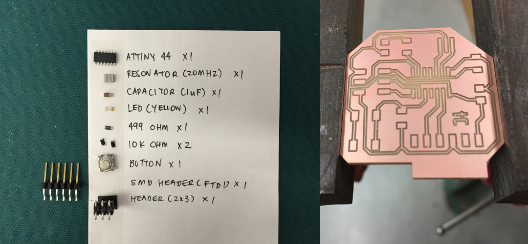
I added most of the parts I needed from the fab library. Initially I tried to net everything together, but it quickly got messy. Naming and labelling my ports made schematic design much easier to manage. You can also do the same thing with ground and power. Routing in the board layout was really hard! I guess there is an intuition that comes with designing circuits over time...
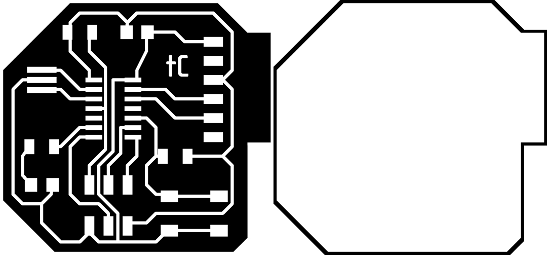
After exporting the (top) traces to monochromatic PNG, I went into Photoshop to create the outline. I added my initials as well as a little lip for the FTDI header so it could rest after being soldered. The Roland Mill cuts the black and leaves the white, which is why the outline colors are inverted.
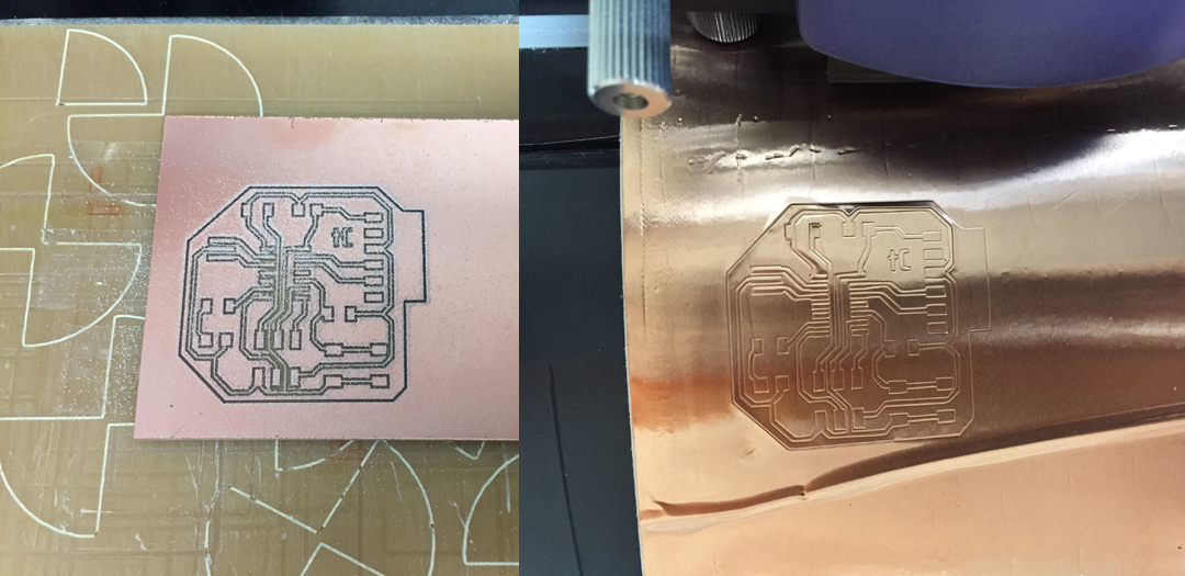
Before sending your job on FabModules, check its calculations to see if all your copper pad are connected and separated where they should. I guess some of my wires were too fine for the default parameters. Instead of redrawing my board in Eagle/Photoshop, I just specified the tool diameter to 0.1mm and offset to 1. This also happened in assignment 03 when I made the alternative fabISP board. I also sent the job to the vinyl cutter -- because why not?
While cutting the outline, I wasn't paying attention to Fab Module's calculations and failed to notice that it didn't compute some of the edges. This is probably because I made the outline in Photoshop and some of the edges were a separate width. Again, changing the tool diameter to a slightly lower value was a quick fix (but maybe next time I'll draw the outline directly in Eagle). Like assignment 03, I must have cut about 20 of my copper traces on the vinyl cutter with no success, wasting A LOT of copper... There is a fine line between not cutting all the way through, and ripping it apart. How can I reach the sweet spot???
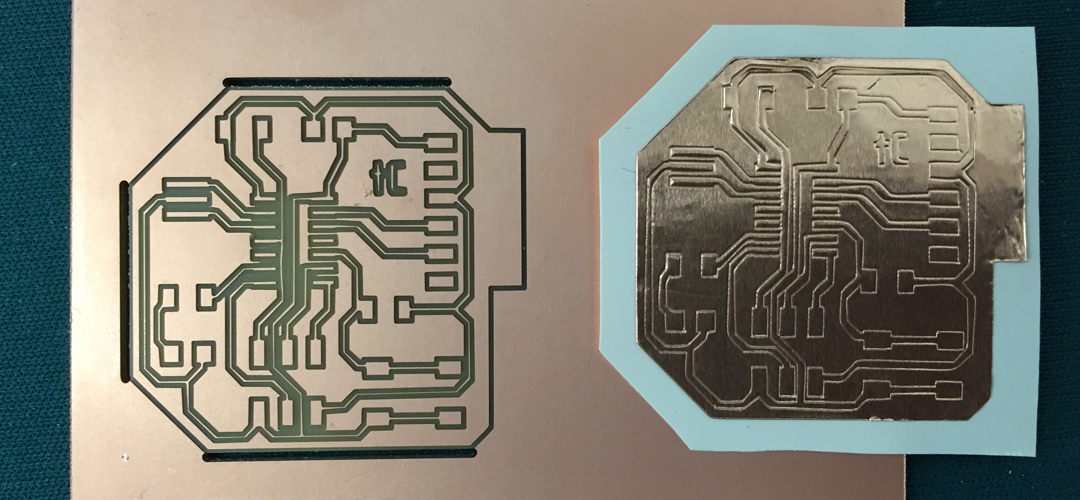
So I just proceeded to stuff my board and forget about my vinyl cutting woes.
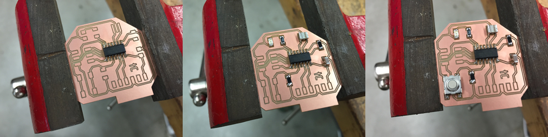
I quickly realized that specifying such a small tool diameter and offsetting only once made this my most difficult soldering task yet.
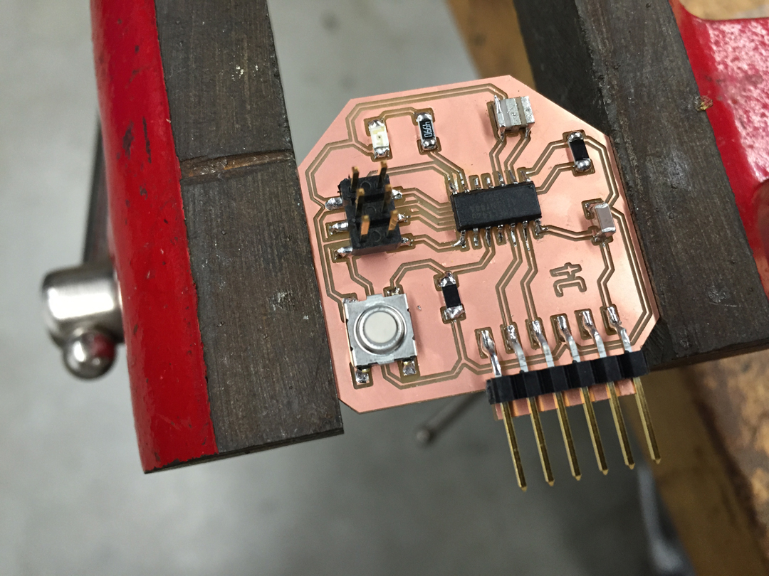
I checked all connections with the multimeter -- looks good! I'm very much looking forward to learning how to program my board for some closure.

This was the other circuit I drew for assignment 03. It was done in Rhino because we hadn't been exposed to Eagle yet. I copied the sizes of fapISP's copper pads and laid them out further apart (I thought it would help with vinyl cutting -- maybe it did, maybe it didn't).