Input Devices
I began this week by adding the new MEMS microphones to the
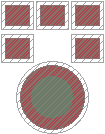
The analog mic: The major difficulty for the footprints was getting the placement right--with chip-scale surface-mount packages like this, the datasheets had precision on the footprints of down to .001mm, which seemed a bit excessive (and was difficult to place).
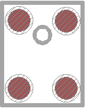
The I2S mic: For this microphone, I ran into issues with the pad sizes being really small and close together. If I have time in future I'll check if it's possible to make the pads small enough/far enough apart to use the 1/64" end mill.
Using the I2S Mic
I wanted to try using the new MEMS digital microphone (Knowles SPH0645LM4H-B), which boasts up to 64kHz sampling at 18 bit precision. On the upside, this is a really cool part, able to do (using two of them) 64kHz stereo audio! On the downside, it wants an I2S clock speed of 2-4 MHz, which should be possible, although this still isn't clear. The advanced idea I'm hoping to be able to get started on is a portable audio recorder to an SD card; to start out, I'm going to try to reimplement Prof. Gershenfeld's analog mic hello-world example, except using the I2S microphone.
I began by reading through the datasheet on the microphone, as well as skimming the I2S specification and the beginning of the SD specification, and doing a thorough reading of the ATtiny44A's USI serial block, which seems like it can (barely) implement I2S, using Timer/Counter0 as a clock source and bit-banging the WS (word/channel select) pin.
But, before I get started describing my implementation, here is the list of considerations in designing this:
-
Clock speed: Getting a clock speed of between 2 and 4 MHz is pretty finicky when working with a microcontroller like the ATtiny44A, which has a native clock speed of 8MHz +/- 10%. I chose to hedge my bets using a ceramic 20MHz resonator, which not only gives me 10 clock cycles between each bit at 2MHz, but also gives me greater precision so that I can be much more sure that I can actually keep the clock jitter under control.
-
Clock generation: The microphone wants BCLK (the bit clock) 2-4MHz, changing data bits on the rising edge for capture on the falling edge, with WS changing on the falling edge of BCLK. I think that I'll use Timer/Counter0 in CTC mode (Clear Timer on Compare Match, that is, frequency generation mode) with the system clock (20MHz) as the clock source and compare match on 4 so that every 5=(4+1) clock cycles (4MHz) BCLK will toggle. This is implemented by setting WGM[2:0] = 0b010 (CTC) in the TCCR0A and B registers, setting CS[2:0] = 0b001 (no prescaling) in TCCR0B, and USICS[1:0] = 0b01 (USI clock toggle on Timer/Counter0 compare match).
-
Clock edge synchronization: I still can't tell whether or not the USI in three-wire mode will collect the data on the right edge or not. From the timing diagram for USI (Figure 14-3) and notes thereafter, it looks like with USICS = 1, the data should latch on falling edge (as it must). However, Table 14-2 and the information on the USICS bits above the table don't seem to mention anything about input latching. I can definitely check this with an oscilloscope, but it would be easier to know in advance.
-
WS generation:The WS signal is supposed to toggle, says the datasheet, on the falling edge that also signals when the LSB (bit 32) is latched. In order to do this, I'm avoiding the USI overflow interrupt, even if it would be convenient for collecting bytes. Instead, I'll be waiting for the interrupt flag to be set, and just poll and clear it. The easiest way to do so is in a macro, so I'll just resign WS to be late in toggling by a couple cycles.
Update! Turns out the overflow flag isn't set until the rising edge, so I can still use it for general waiting but I'll need a special set of masks for checking the USI counter value to check when to toggle WS. I've realized that my code to wait for the next byte could allow me to do up to 2 bytes of other stuff (15 bits * 10 clocks/bit = 150 clock cycles free to read stuff) unless WS needs to be toggled after one of said bytes.
A quick note on why Windows is annoying: Tried to link my code into the git repository by placing a symlink in the repo; instead it just moved a copy of my code into the repo. I think that it'll work to do the reverse by editing the copy in the repository and linking to it with a Windows shortcut in the original Atmel Studio folder.
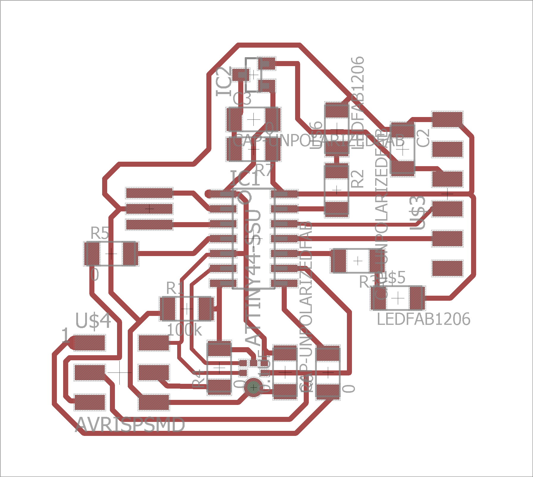
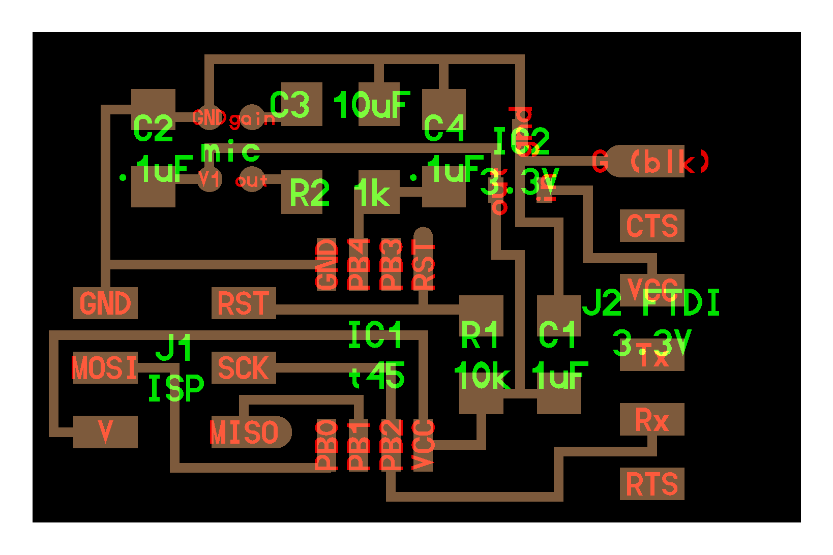
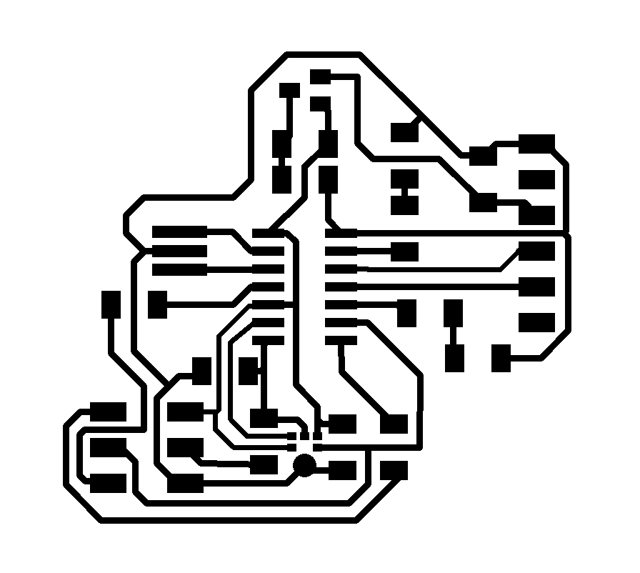
Designing the board
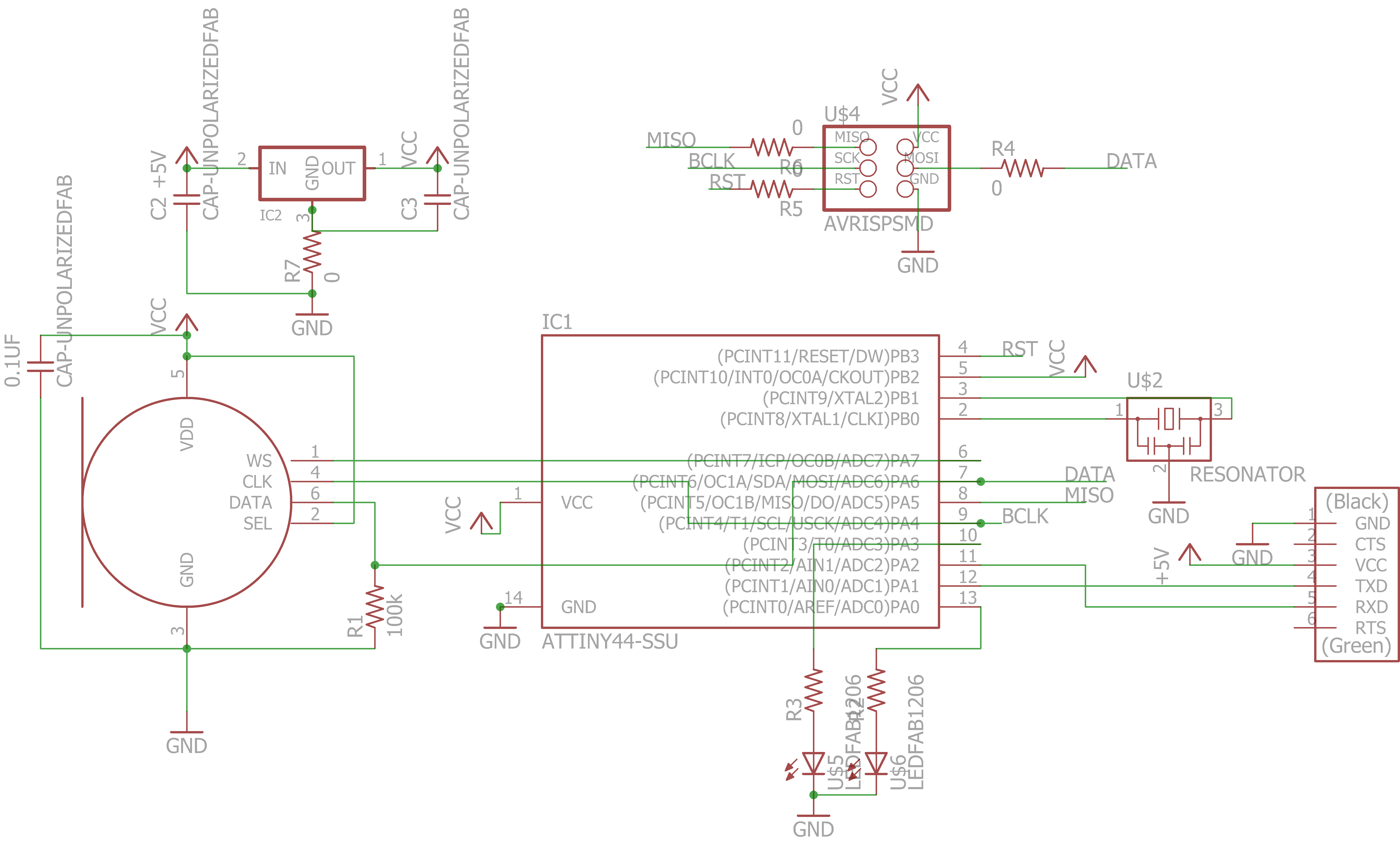
The I2S microphone board schematic: I was trying to reproduce Prof. Gershenfeld's MEMS microphone board with the I2S MEMS microphone. Here is the schematic for download.
In designing the board, I tried to fit what was needed for the microphone, as well as an FTDI header and some indicator LEDs. It worked out, albeit with a few jumpers. Unfortunately, the I2S mic gave warnings in the DRC--it seems that the pads are too close together for the 1/64" end mill.
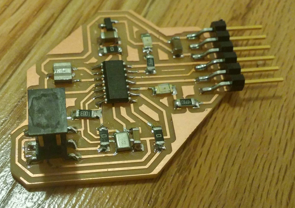
Mic board: I finally got it soldered, but couln't test it out because the Harvard lab lost all of its 3.3v FTDI cables.
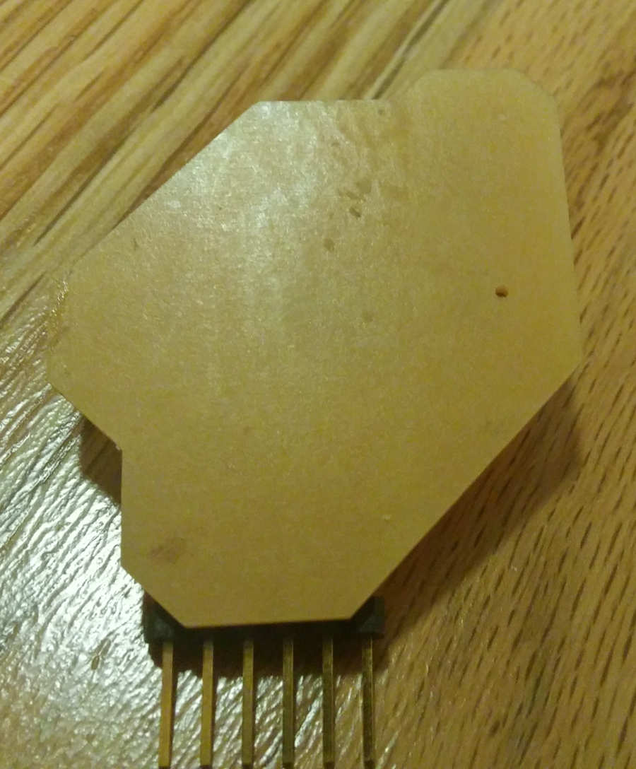
Sound hole: I'm still surprised that the microphone is supposed to get audio through that little hole.
Code!
I put all of the things discussed above into my code, which uses the USI in three-wire mode to read data from the I2S data line. The code can be downloaded as an Atmel Studio project here, or you're welcome to peruse the separate files here.