Week 3: Electronics production
This assignment was one that I'd already done in past: I learned how to use the Modela last year in the Harvard lab, and spent a lot of this past summer doing electronics design, embedded programming, and soldering prototypes. This time, when making the ISP, I made a small modification that I think will be useful in future: I added a switch to allow me to choose whether the USB power solder jumper was closed.
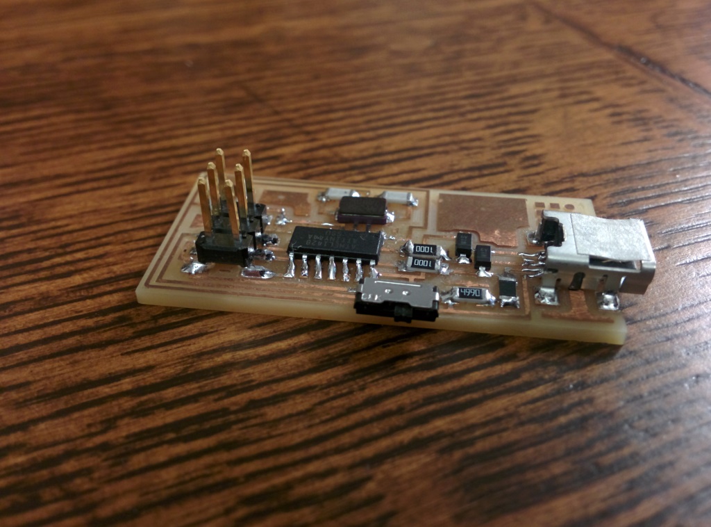
Fab ISP: Here's my completed programmer. In front you can see the switch I added.
The ISP consists of four main sections: the USB interface, the microcontroller , the clock and the programming header. The USB interface consists of a mini-USB type B port, with the 5v and ground lines going to the microcontroller (and the rest of the board) and the two data lines going into 100Ω resistors with a 3.3v Zener diode clamp. This prevents the microcontroller from frying the USB port with too-high voltages. The far sides of the 100Ω resistors feed into two pins in the microcontroller. The microcontroller is an Atmel ATtiny44A running at 5v and 12MHz clock. Although it doesn't have hardware USB, apparently it's able to handle basic bit-banging USB in software. The clock is a crystal oscillator, 12MHz nominal frequency with a very high precision (parts per million, I think). Its load capacitors feed straight into the ground line. Finally, the programming header is a 2x3 header with .100" pitch, using the standard pinout for AVR ISPs so that it can program any board that uses an AVR microcontroller.
Here I should probably point out why it's important that I put in that switch. The switch doesn't do very much--on one side, it will power the target board from the USB port, on the other side it won't. Importantly, this allows me to run simple boards (where by "simple" I mean only that they don't have high-current output devices) off of my computer without having to attach a separate power cord. On the other hand, the switch allows me to disconnect the power line for boards that have batteries or require high-current power sources. This prevents bad things from happening with voltage mismatches between the target board and my computer's USB ports.
Producing the board was pretty simple. After it was cut on the Modela, I soldered the components on, replacing the zero-ohm jumper with a switch connecting the USB Vcc line to the programming header. I helped a couple other people learn how to solder, then came back the next day to program my board. After desoldering the one jumper and plugging the board into my computer, I noticed that the ISP is listed as a USBtinyISP, another ISP that shares some genealogy with the FabISP.
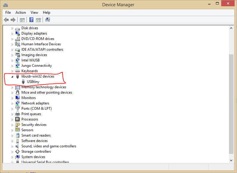
USBtiny: Looking at how the ISP shows up in the Device Manager.