Output Devices
Ah, to have an extra week to work on the assignment. That part was nice. On the downside, my plan to implement a portable, speed-controllable fan using an old desktop computer fan was interrupted by blowing out the fan I was planning to use. So instead I started working on a stepper motor driver, which I hope will work after I program it.
A portable fan
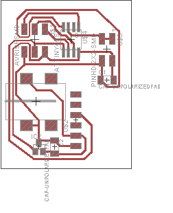
The fan driver: PC fans conveniently can be plugged directly into 12v power supplies, so this will work fine for any two- or three-wire fan, and the fourth pin, which is intended to be PWMed by the microcontroller, can switch a JFET internal to the fan.
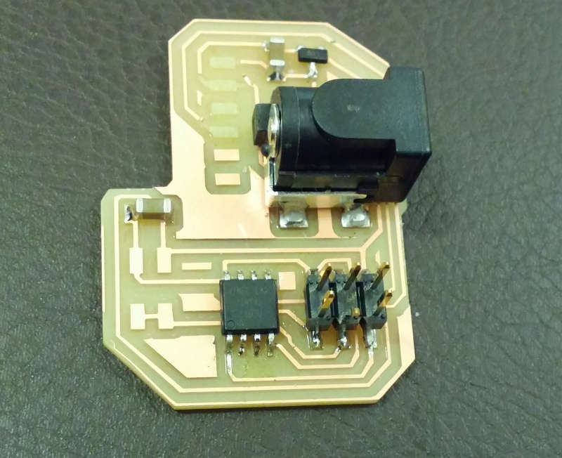
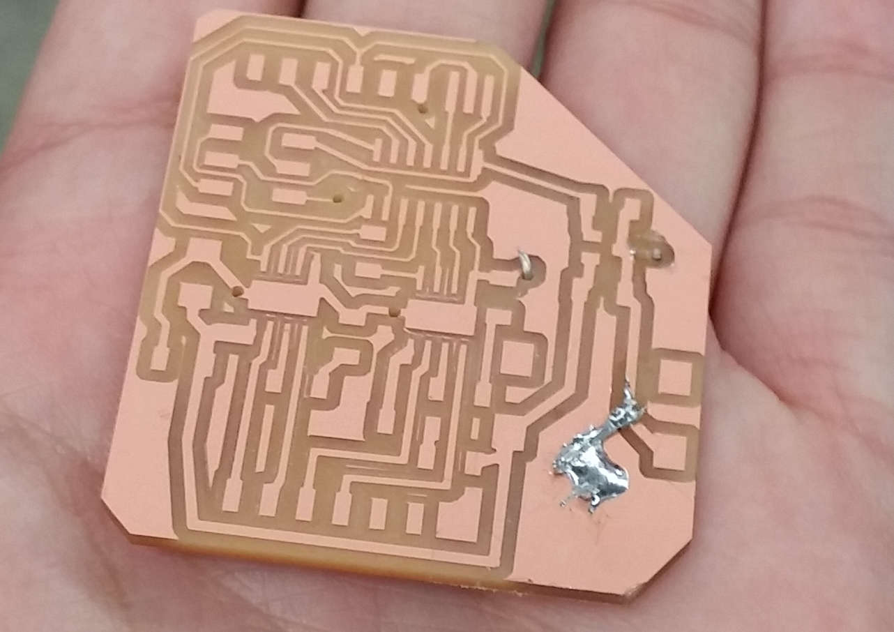
Soldered and broken: I succeeded in soldering the fan driver, but the fan pins broke off in my backpack. Here's a photo of what it looked like afterward.
For better or for worse, I've taken to using the FTDI headers to mate with all sorts of female crimp connectors, including the ones for these fans. I got one of my fans to work (the 3-pin one that takes 500mA, so it couldn't be used for my portable fan), but since it didn't have the PWM pin, it was a rather uninteresting demo.
But then I fried the fan that I was planning to use for the portable fan. I'm still not quite sure what was wrong with my setup: I just plugged it into the board with the microcontroller unprogrammed, so it should've simply spun at full speed; however, instead it started smoking. I think (but don't know) that I'd gotten it to spin before, but perhaps it was always fried. Either way, this project was only feasible with a fan that took below 300mA: I'm planning on running off a 2200mAh, 3.7V Li-ion battery powering a boost converter to get to 12v. The massive current reduction in the boost converter would mean that I'd probably need around 400mA out of the battery for every 100mA consumed by the fan; above a couple hundred mA on the fan side would mean more current than I should source from the battery.
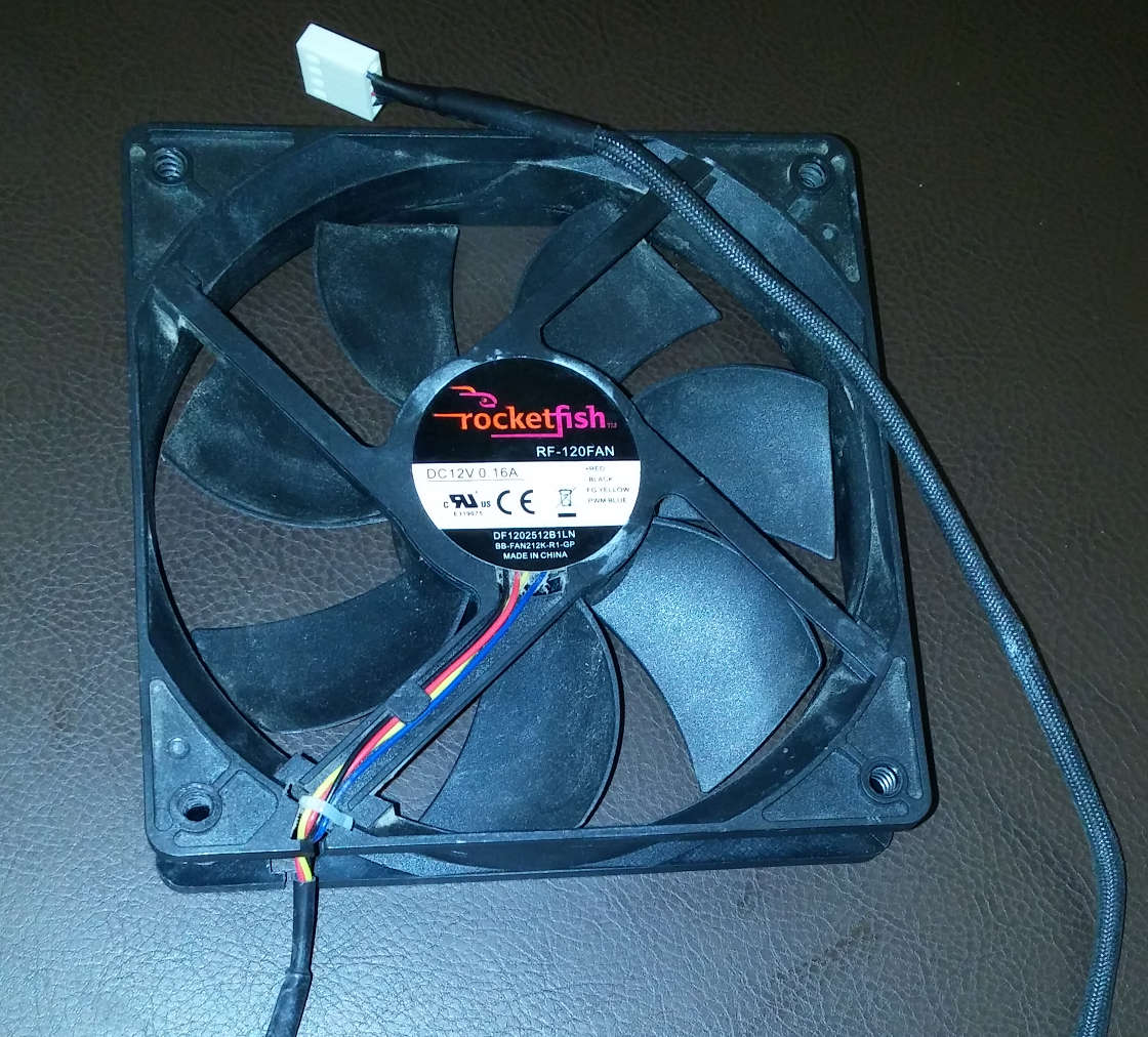
Broken fan: this nice Rocketfish fan was the only one I could seriously consider using, as it only consumes 150mA and still pushes a lot of air (it seems pretty new).
A Stepper Motor Driver
So I switched to working on something for my final project, a bipolar stepper motor driver using two Allegro H-bridge chips. I'm still thinking of trying to make a desktop CNC mill, so I need to figure out how to drive the three translational axes to actually move the end mill with respect to the machine tool. I've used the Pololu driver carriers in the past (which were nice and straightforward), but working at this lower level was also interesting.
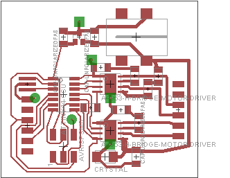
Designing the stepper driver: After beginning with a one-sided design, I gave up when I realized that I'd have more than a dozen jumpers, and switched to a two-sided board with the second side only a ground plane, preventing the need for learning to cut the second side.
In terms of electronics design, this was pretty straightforward. The H-bridge chips have internal switching current control, so I merely needed to add some sense resistors at the LSS pin in order to limit the current to whatever the stepper could handle, 1A in this case. For maximal flexibility in designing communication with the driver, I included a FTDI header; I realized in hindsight that it's quite doable to use the ISP header as an I2C header or general communication header, if I wanted to use the Tiny44 as either a Step/direction controller or to implement more advanced step counting and speed control.
I made one important mistake when cutting the board the first time: I forgot to include the vias layer in the image I used to cut the traces, so I didn't have any pads to solder to when I soldered the vias.
Missing via pads: I tried to solder them anyways, but it didn't work super well.
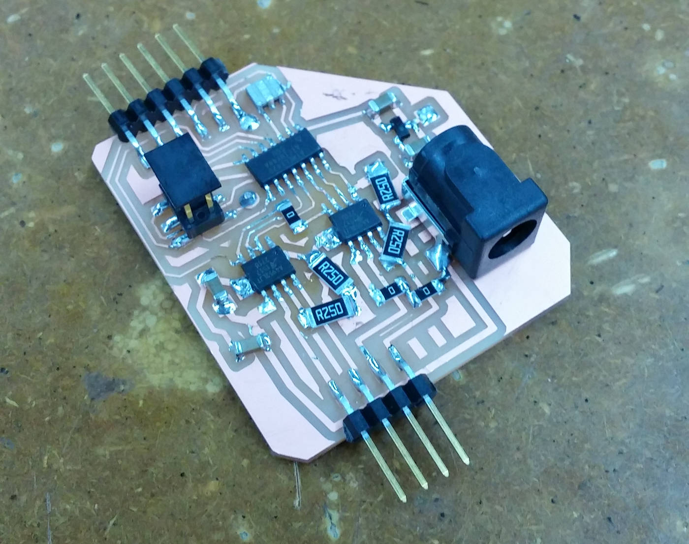
Soldered driver board: The oversized 0.25 Ohm resistors didn't fit on their pads, but otherwise I had no problems.
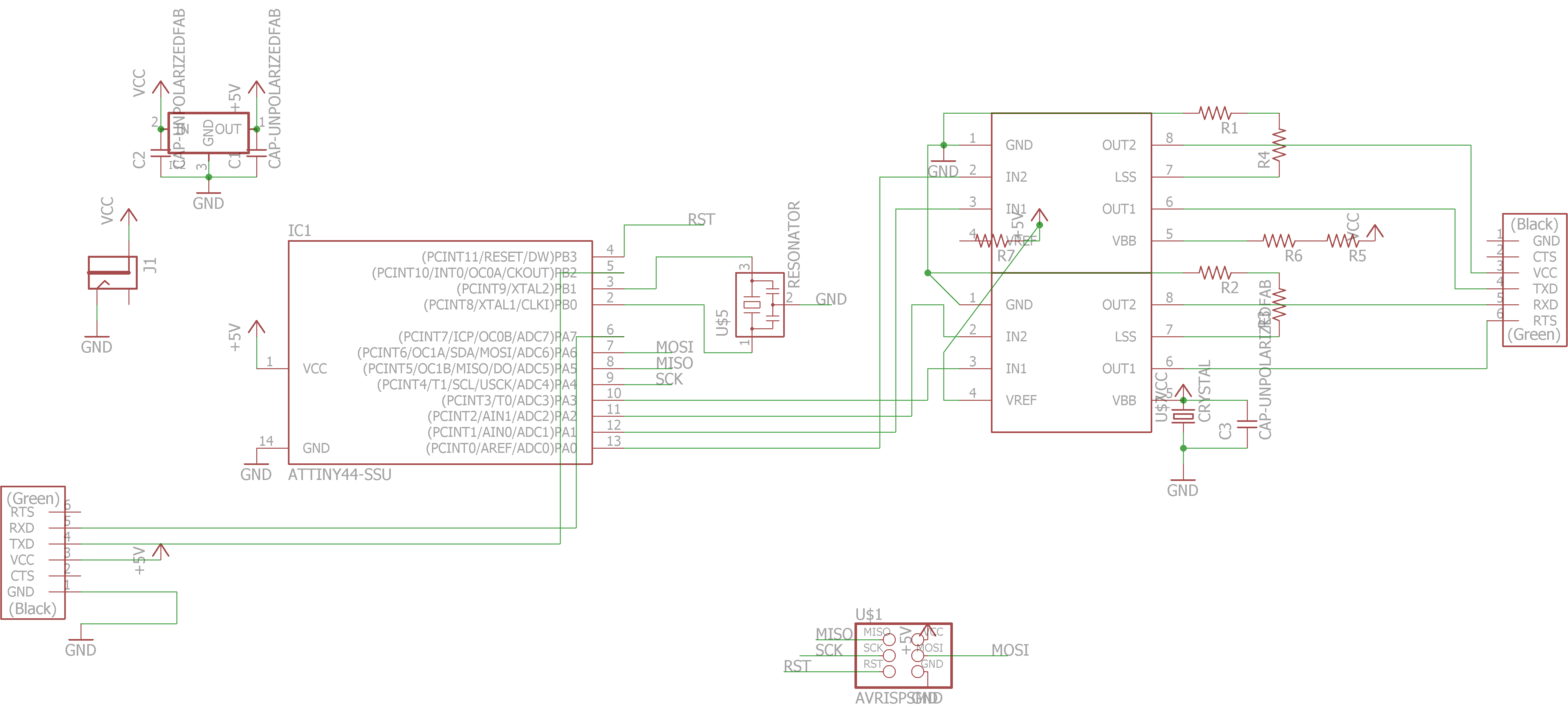
Stepper driver schematic: I took advantage of the hardware PWM of the stepper motor drivers, putting current sense resistors on the LSS pins
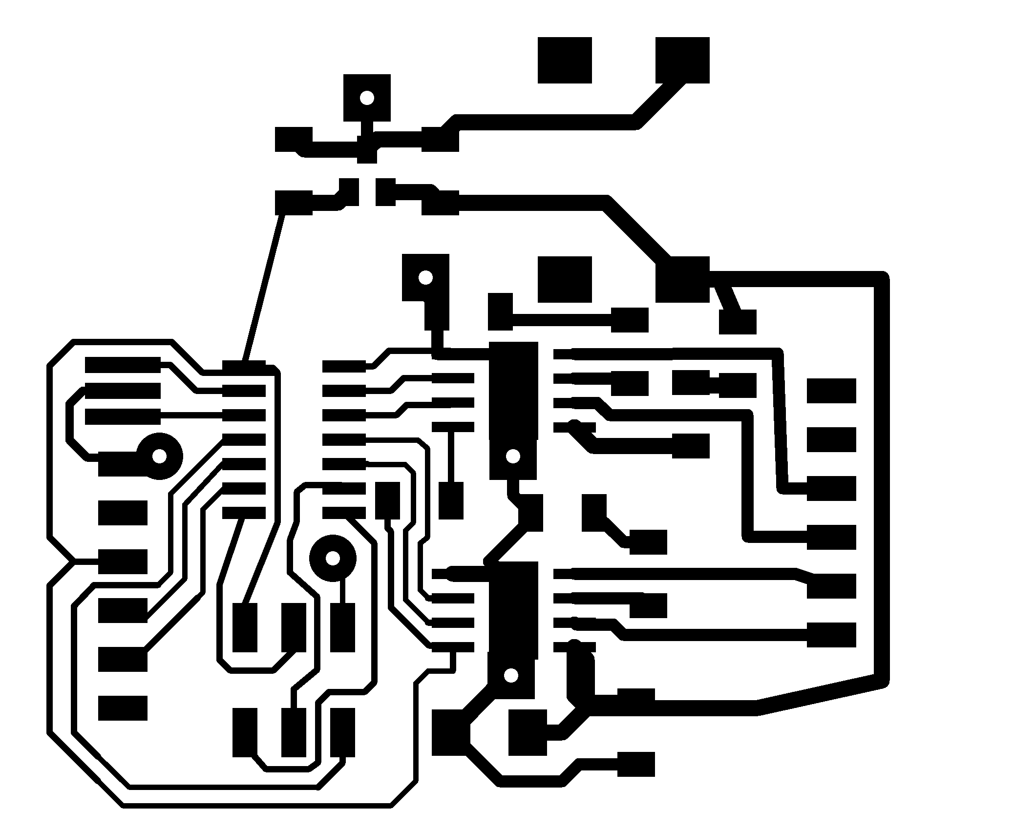
Traces: This time with the pads.
Outline + holes: Somehow, Eagle knew to automatically treat the inside of the vias as white, making it easier to mill.
If you'd like to download the Eagle design files, they can be found here.