How to Make (almost) Anything
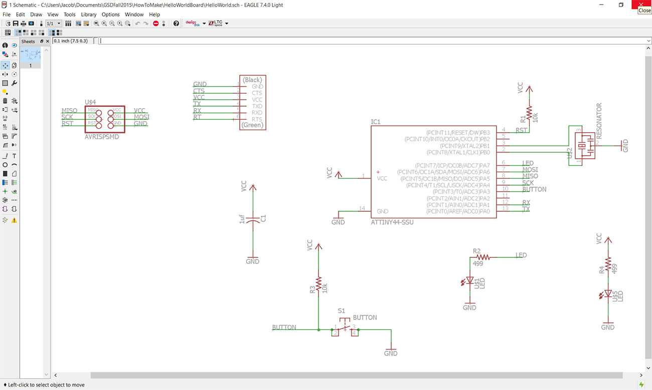
This week we were asked to redraw the echo hello world board, add a button and LED, and then make it. We could use any software that we liked to accomplish this, so I chose to use the EAGLE PCB Design Software which was highly recommended. The first step in this software is to lay out a schematic for how the circuit will operate, which involves knowing which components you will be using. I was able to import the fab.lbr which is a library containing all of the components that would be necessary for this assignment and made the selection process much easier. These are the components that I ended up using:
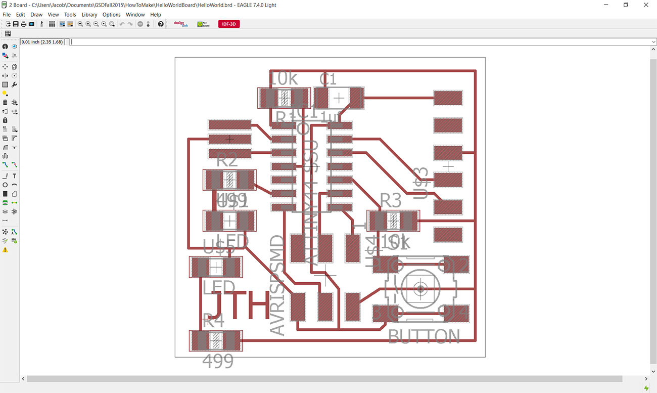
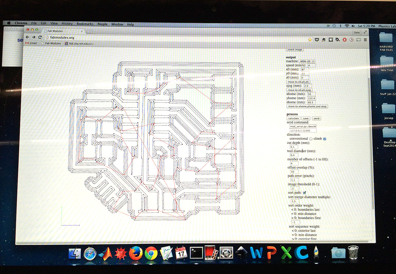
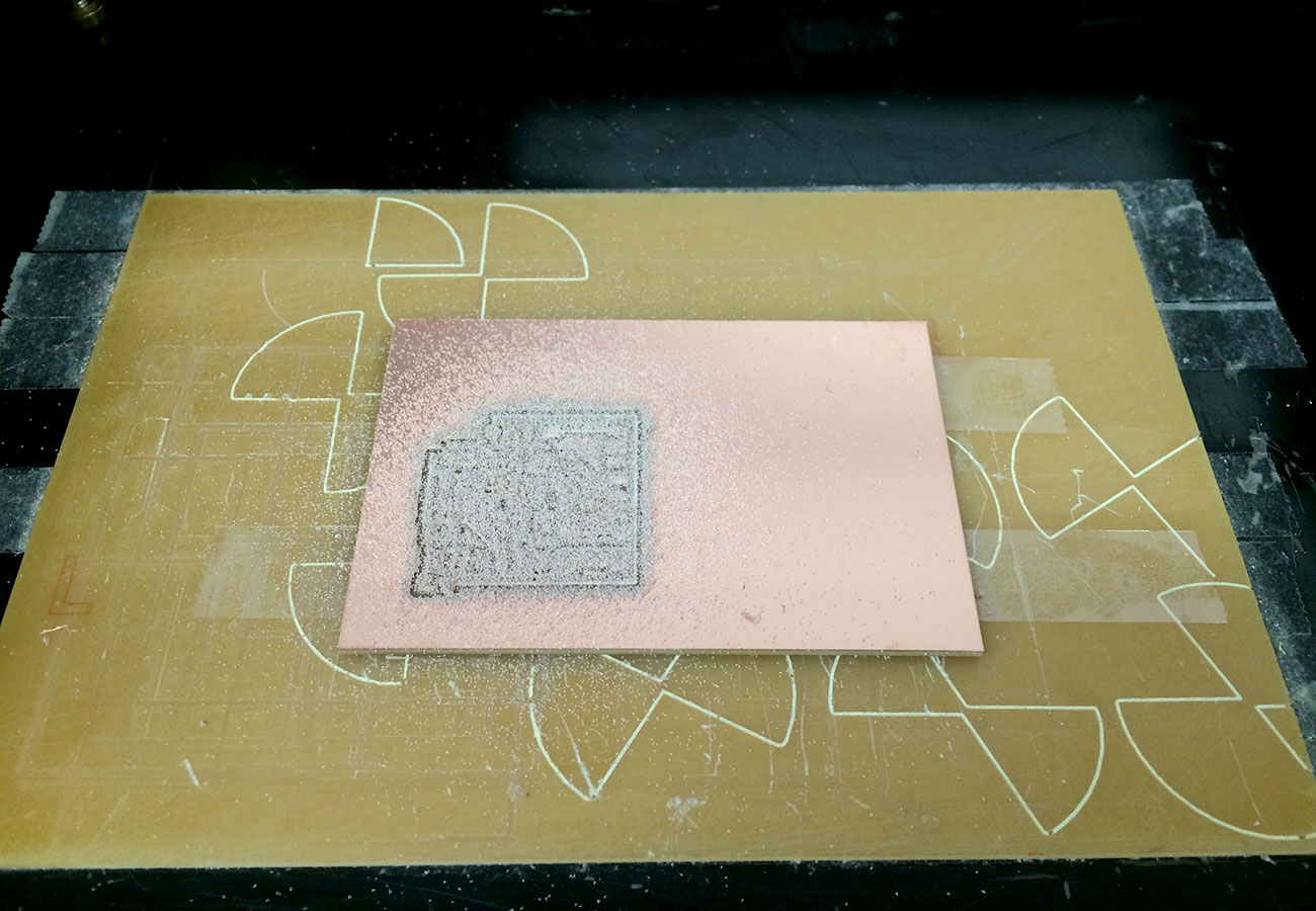
After laying out the components and creating "nets" between them, you can switch to board view where you position the elements as they will end up on the board and generate routes between them which will become the traces. The routing step is slightly challenging as you do not want traces to cross over each other, but if viewed as a puzzle can be enjoyable. After the board layout looked good, I exported the traces and outline as separate .png files to then mill on the Roland.
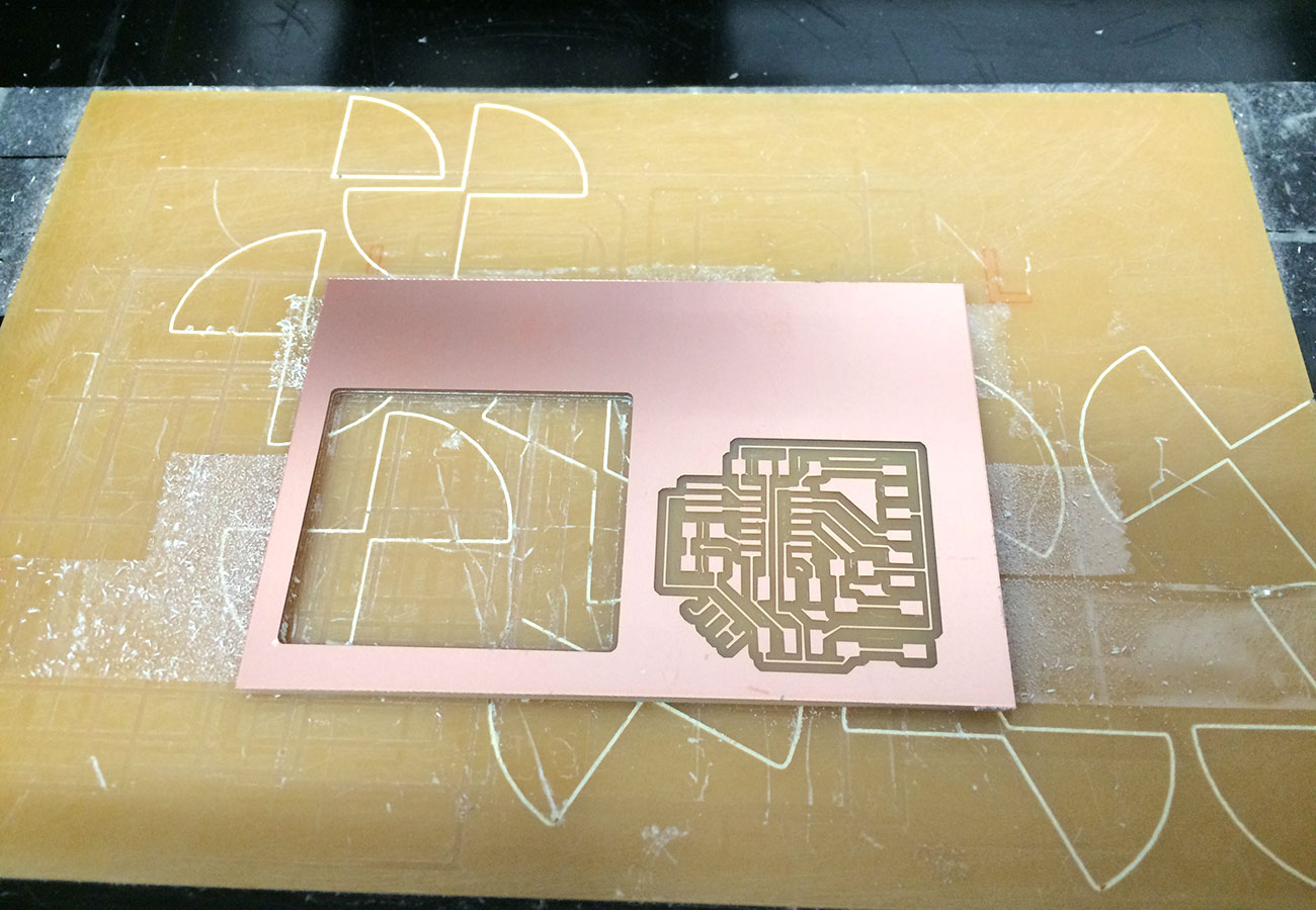
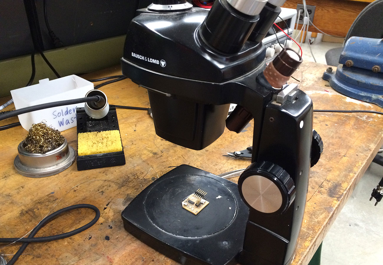
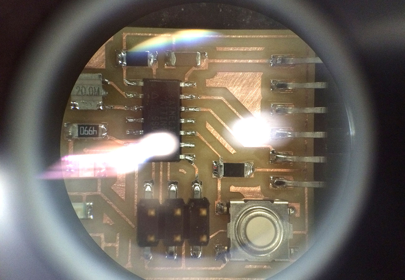
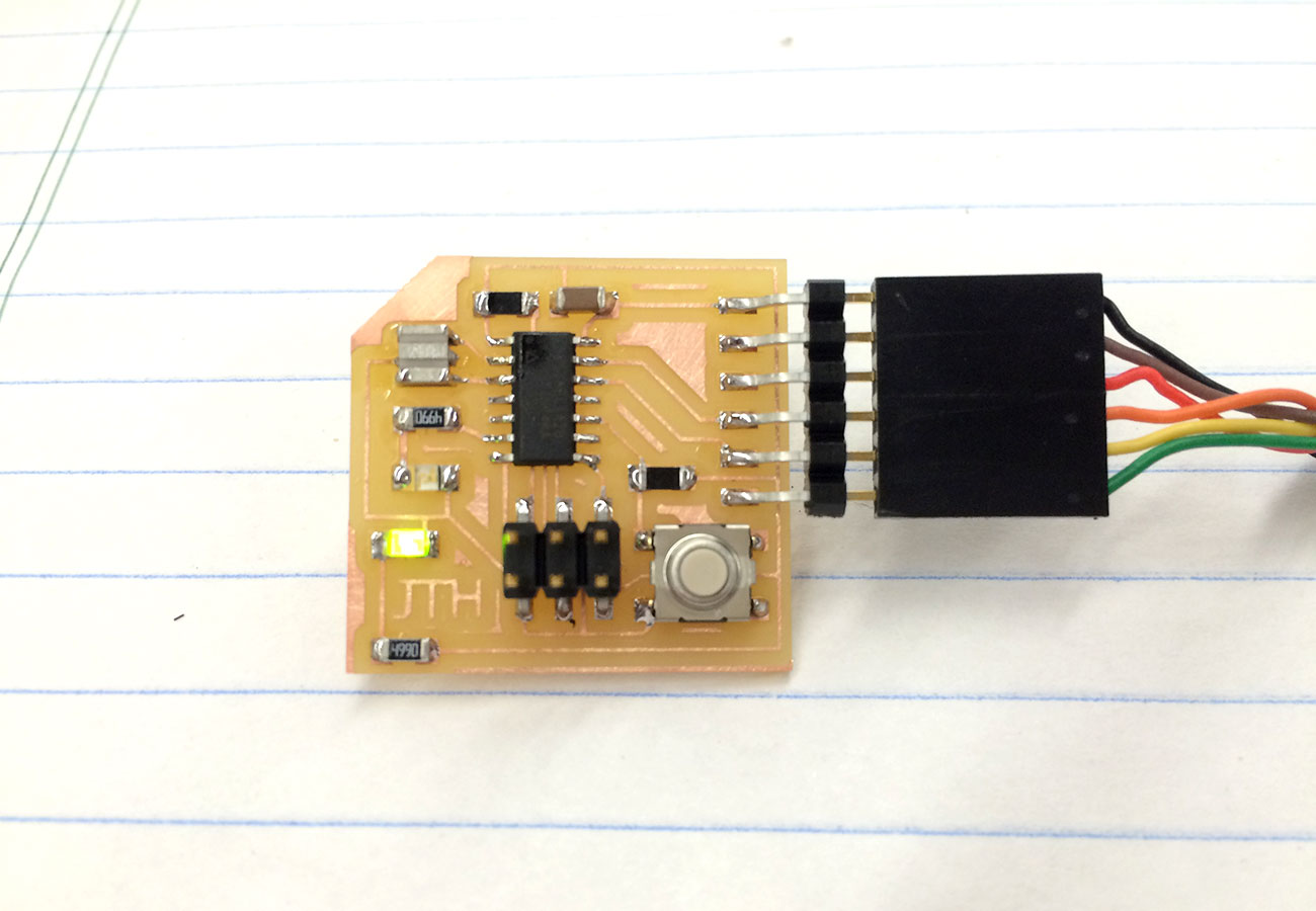
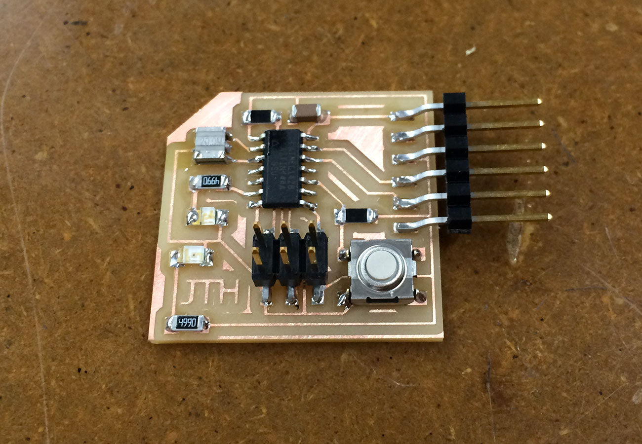
Once I had my milled pcb, I went to work stuffing it with the components, starting with the FTDI header, 499 Resistor and green LED to confirm that the traces were good and the board was recieving power. I used the microscope while soldering the components on this board, which I found to be very useful for the ATTiny 44 pins.