How to Make (almost) Anything
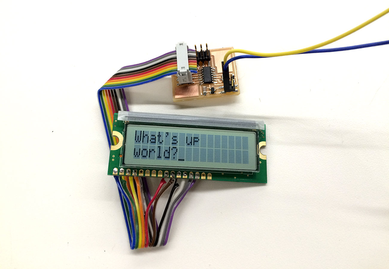
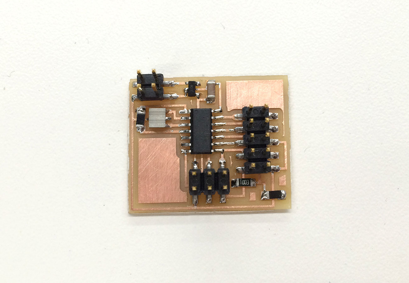
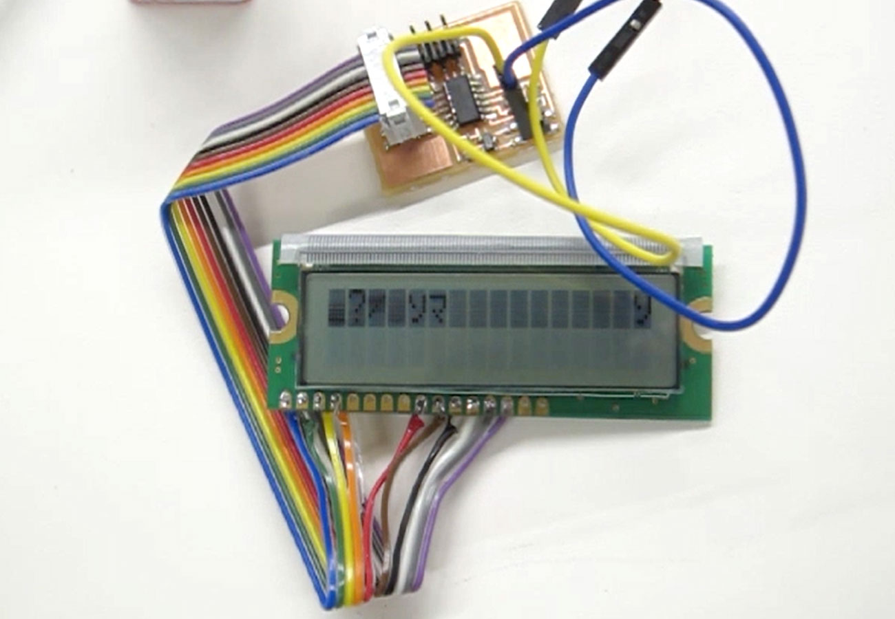
This week we were asked to add an output device to one of our microcontroller boards and program it to do something. I've been wanting to explore the use of an LCD screen as a possible feature that I can add onto my surfboard for displaying water temperature. I was also eager to get the rf modules working which I had started during embedded programming week. For the LCD display I used Neil's mill files and c program on the fab website. The board layout was pretty straightforward and I was familiar with all of the components except for the 5V regulator, which was nice to have as I ended up using a 9V battery to power the circuit. At first I had some difficulty understanding the pin layout for LCD screen as the datasheet is pretty sparse. I was able to confirm the correct pins to attach the ribbon cable to by looking at the setup in this video.
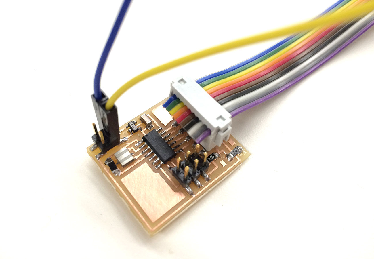
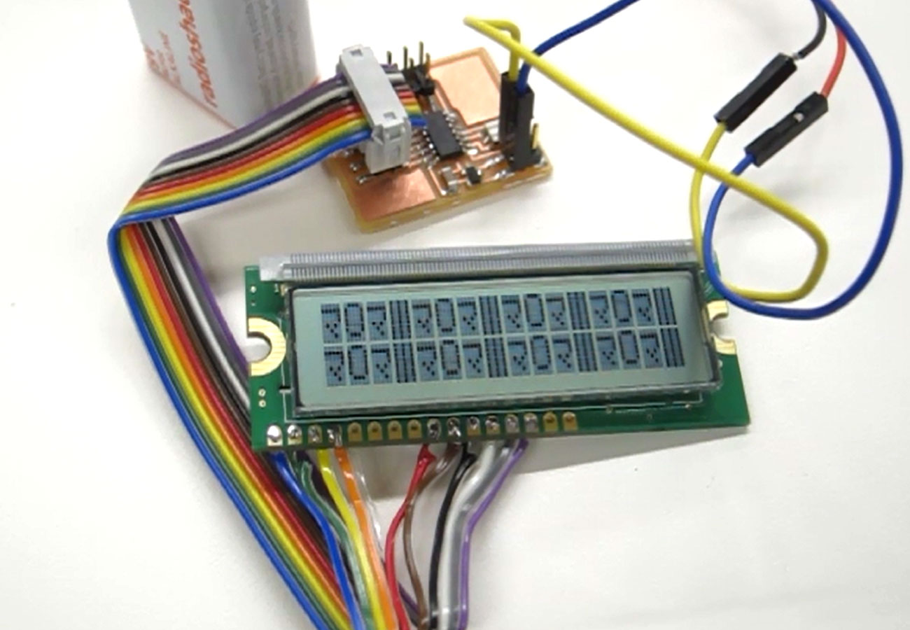
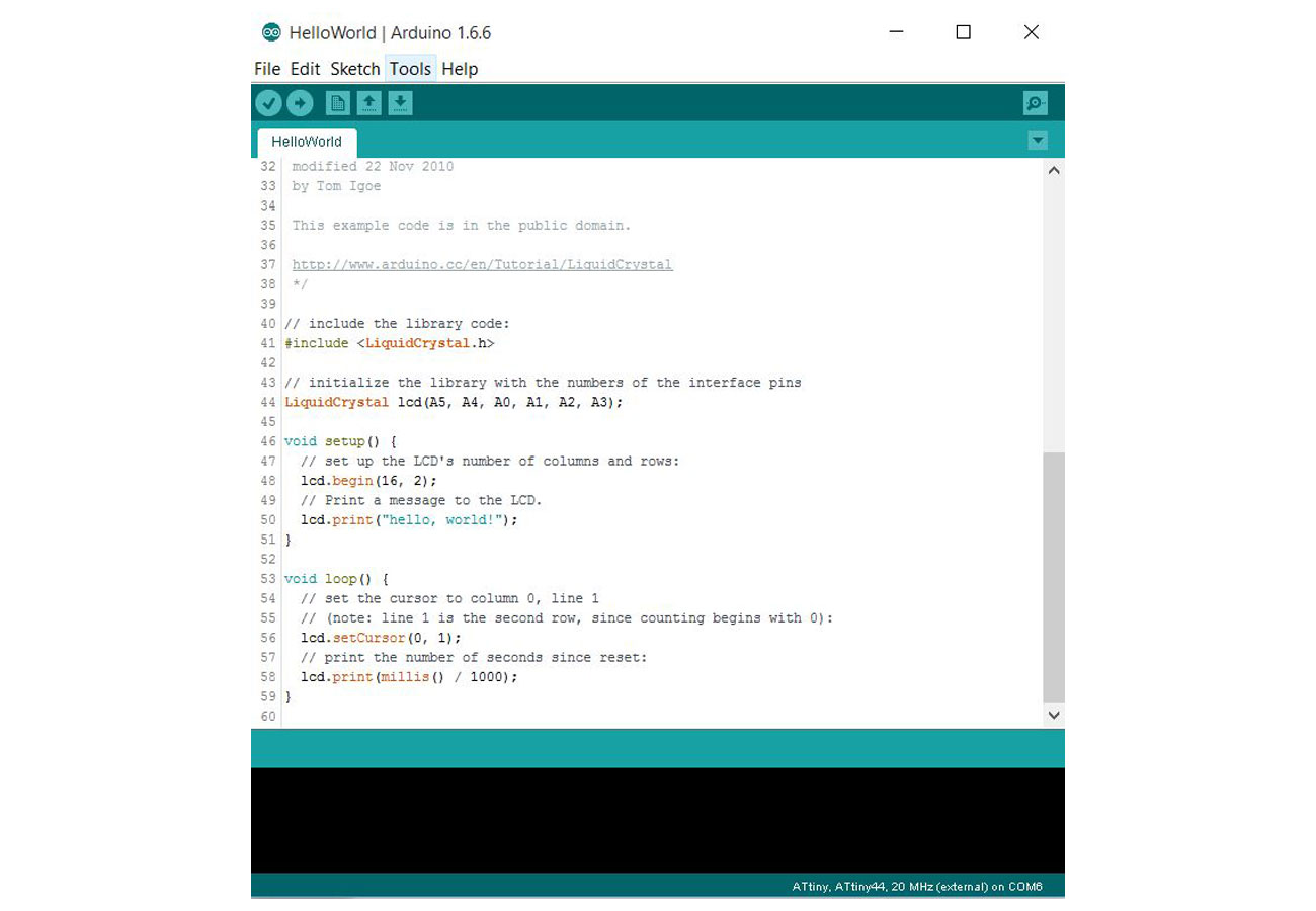
After the board was stuffed, I was able to program it using my fabISP. However, because I am using the Arduino IDE, I needed to install the ATtiny support using the built-in boards manager by following this tutorial. I could then select ATtiny board, ATtiny 44 processor, 20MHz external clock, and USBtinyISP programmer. I copied Neil's c program into the IDE and uploaded the sketch. Then I plugged in the ribbon cable to the LCD screen and got the "hello world" read out! This did not happen on the first try and only worked after I completely re-soldered all of the ribbon cable connections to the LCD screen pins. I also wanted to try the Arduino LiquidCrystal library as there are some interesting sketches, but I was unsuccessful at getting the characters to print out properly. I think there must be something minor that I am missing, but for now I only get garbled characters.
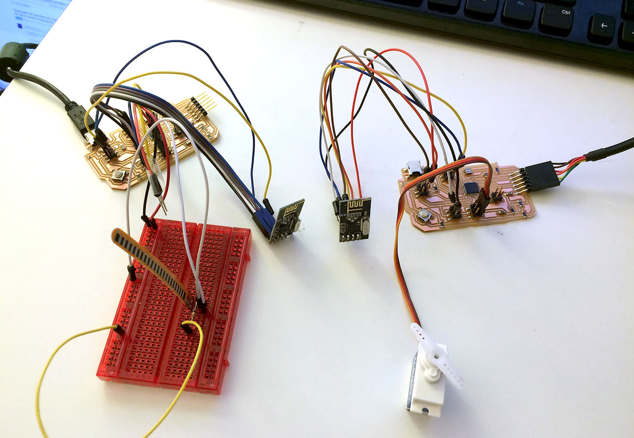
This week, I also continued the work that I had started in the embedded programming week by getting my two fabduino boards to communicate using the rf24 modules. The boards that I am using are based on Dan Chen's design as described in his great Networking and Communications page I made a slight tweak to the design in that I replaced his clock with a 20MHz resonator, which ended up causing me lots of problems when trying to upload sketches.
After much searching and editing the bootloader and boards.txt files, I finally found a resource which had already figured out how to properly designate an ATmega328p with 20MHZ external clock in the Arduino IDE, located here. Once I installed this package using the board manager, I was able to burn bootloader on my boards and upload sketches. The code that I used is also derived from what Dan Chen already figured out, and I uploaded the sender sketch to one board and the reciever sketch to the other board. Opening the serial console in the reciever sketch demonstrated that the board was recieving signals from the sender and then I was able to add a few components to test out the latency.
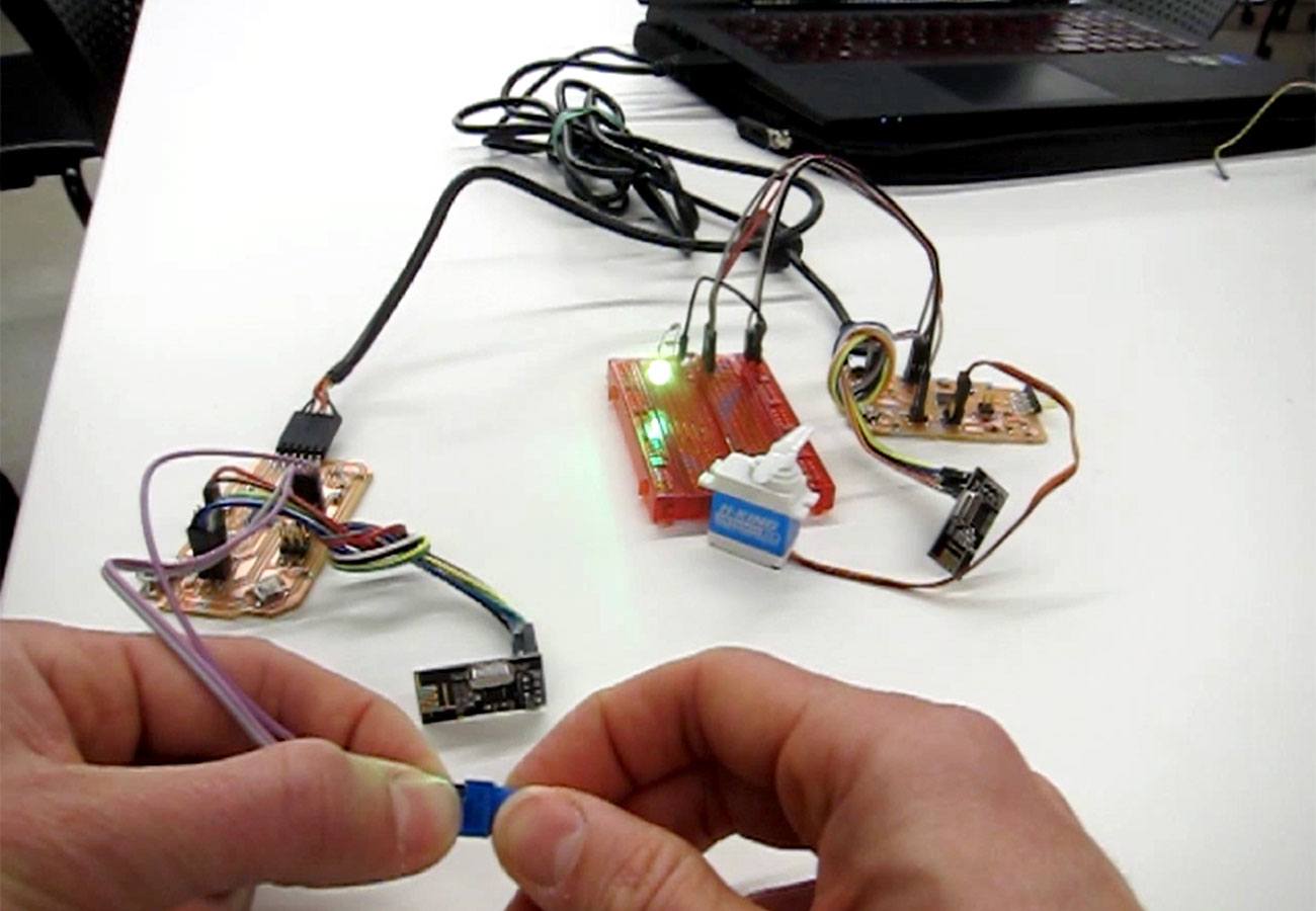
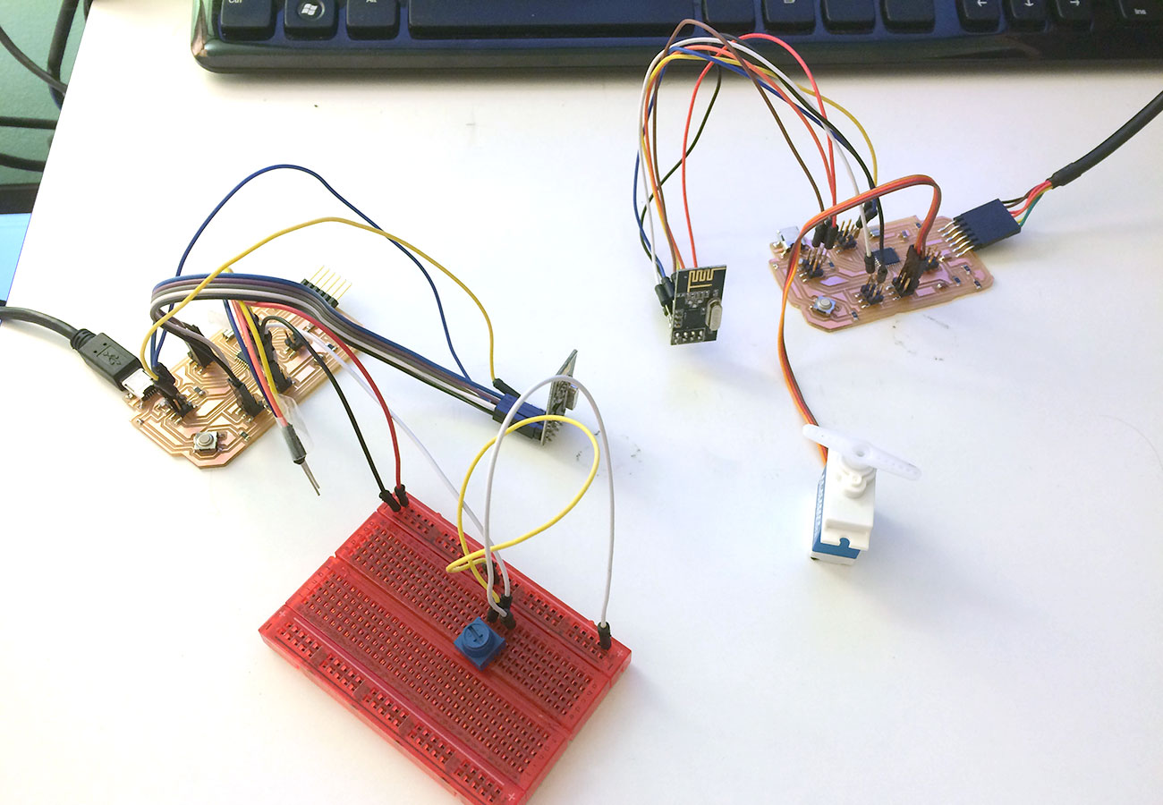
The ATmega328p is a great chip for this exploration because there are so many available pins. This allowed me to set up the reciever board with a servo motor as well as an RGB Led. I experimented with both a potentiometer and a bend sensor on the sender board, which both had pleasing results in terms of response time. The values for the potentiometer were mapped from 0-1023 to 0-180 for the servo and 0-765 for the RGB led. For now, I just have the led set up in a breadboard and have the code set to transition through the different possible color combinations base on the input value, although the blue value does not seem to be working as it should. I remember hearing that the blue led needs lower resistance, which I tried so I still need to figure that out. The other thing that was strange is the range of motion for the servo was never quite making 180 degrees.