.jpg)
.jpg)
DEC 14, 2015 ||| Skills: Rhino, Eagle, Arduino ||| Material: Copperboard, LED, Hall Effect, Plexi, PLA filament
I started my project with the realization that given a little more than a week, I don't have time to make an pair of shoes and do all the electronic designs. I decided to reduce the ambition to a pair of clips that would go on the back of a pair of existing shoes. .jpg)
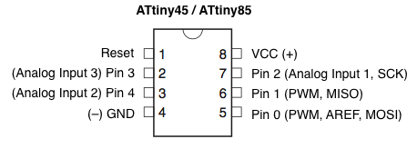
Designing the circuit board I broke the problem down to three parts: reading the data from hall effect, lighting the LED strip, and powering the board. First, continuing the investigation from input week, with the help of Sam, we figured out the problem with the arduino code was that the incorrect identification of the analogPin. Looking at this diagram, I realized that the analogPin number is a third number other than the original or the arduino conversion. So after figuring that out, the serial monitor was able to print out the correct output. However, a bigger problem was that not only was the data jittery, the scope of distance for the hall effect to take effect is much shorter than a stride. Initially, Sam suggested me to make a phototransistor to see if it yields better result. However, the distance was even more limited.
.jpg)
While it's unfortunate that the project couldn't calibrate a further distance, Sam told me to include a line of code looping that basically takes the average of the measurement in order to smooth out the data.
" for (int count = 0; count < 255; ++count) {
val = analogRead(analogPin) + val;
}"
Next, I hacked my board from output week to connect it to an Adafruit Neopixel LED Strip just to test out how it works and implement a fade function. After downloading the Neopixel library from github, I used the example strandtest and simple codes under the library to make sure that it works and then started writing a code to initiate a fade sequence. Initially, the fade code from embedded programming week was more like a transition between colors, but then using the setBrightness function, I was able to make it dim in and out independent from the color. Next, I had to combine the first two parts and I wanted to just hack them together to test it out. However, a big problem with using arduino and including the Softwareserial and Neopixel libraries is that they take a lot of memory, and I had to change my board design around an Attiny 84 instead. After designing a new board, I was able to set on this code to have the R and B values respond to the distance, the lights fade in and out independently, and using the B values as a way to turn off the lights once the magnet is out of range.
.jpg)
Next, I decided to switch to fabricating the physical object, because I need to place the hall effect and magnet in place to better calibrate the distance. Initially I wanted to include a 9V battery in the clips, but after making the prototype, I really did not like how chunky it looked and decided to make the battery a separate piece and slim down the design of the actual clip. I decided to stack 1/8 plexi for the outer shell and sandblast it to give it a frosted look. The inside casing would be 3D printed to fit the curve of the shoes and enclose all the electronics. Because the hall effect is so weak, I had to find a way to locate it on the outside of the clip instead of hiding it on the inside with the board (this was extremely tricky to solder later on). I decided also decided to use Velcro to attach the battery pack to the shoe laces.
.jpg)
One last big of hurdle came when I attached a 3 AAA battery pack. First, I forgot that I had placed a 5V regulator in the initial schematic because I was planning on using a 9V battery. Because the combined current of three 1.5V batteries is only 4.5V, my board wasn't able to respond and I had to remove the regulators. The other problem was that I noticed that the distance I had calibrated between the two magnets somehow changed when I switched from FTDI powered to battery powered. So one of my clip wont turn on and the other one won't turn off. This was extremely problematic because I suspect that the current drop from USB to batteries changed the reading of the hall effect but I couldn't turn on serial monitor again without attaching it back to USB power. So I basically had to keep changing the Bval through trial and errors until it was working. It wasn't the most accurate way, but I couldn't figure out a better way...
.jpg)
In the end, the result was a pretty good prototype of what I want it to do from the beginning. Rather than focusing the the distance between strides it became more of a interaction between the stationary distance of two feet. And as I was trying to demonstrate the different colors to my friends, I had to awkwardly change my feet and the had to make them work with one another. One of the biggest problem in terms of design are the magnets on the outside. Because I switched the polarity between them in order for one hall effect to get bigger number as the magnet approaches and vice versa, they stick together when the clips get too close. And if I were to work on a version 2, I would definitely find a better sensor to accommodate a bigger range. All in all, I was able to combine a lot of different skills from different weeks into this final project, and I'm very satisfied that it worked!
Final Arduino Code // Schematic