final project: interactive brain
For an integrated final project, I decided to make an interactive toy brain. I wanted to use some form of pressure sensing via testing the step response of plates embedded in a rubber brain to make the brain give specific output depending on where it is poked or squeezed. A fully realized version of this could, for example, have topologically arranged sensings such that if you poked a specific brain region, it could output audio telling it what it is ('primary motor cortex', etc...). As a prototype of such a system, I designed a brain that could output audio or light depending on whether one of two spots are compressed
brain design
Given more time, it would have been amusing to get an MRI scan of my own brain, and use that as the template for a design (this can be done, e.g., by voltuneering for an fMRI study, asking for your scan data, and using the free software suite FreeSurfer to convert it to an .stl file). Instead, given the compressed time schedule of the project, I found an .stl file using Yobi3D (a good online database of .stl files).
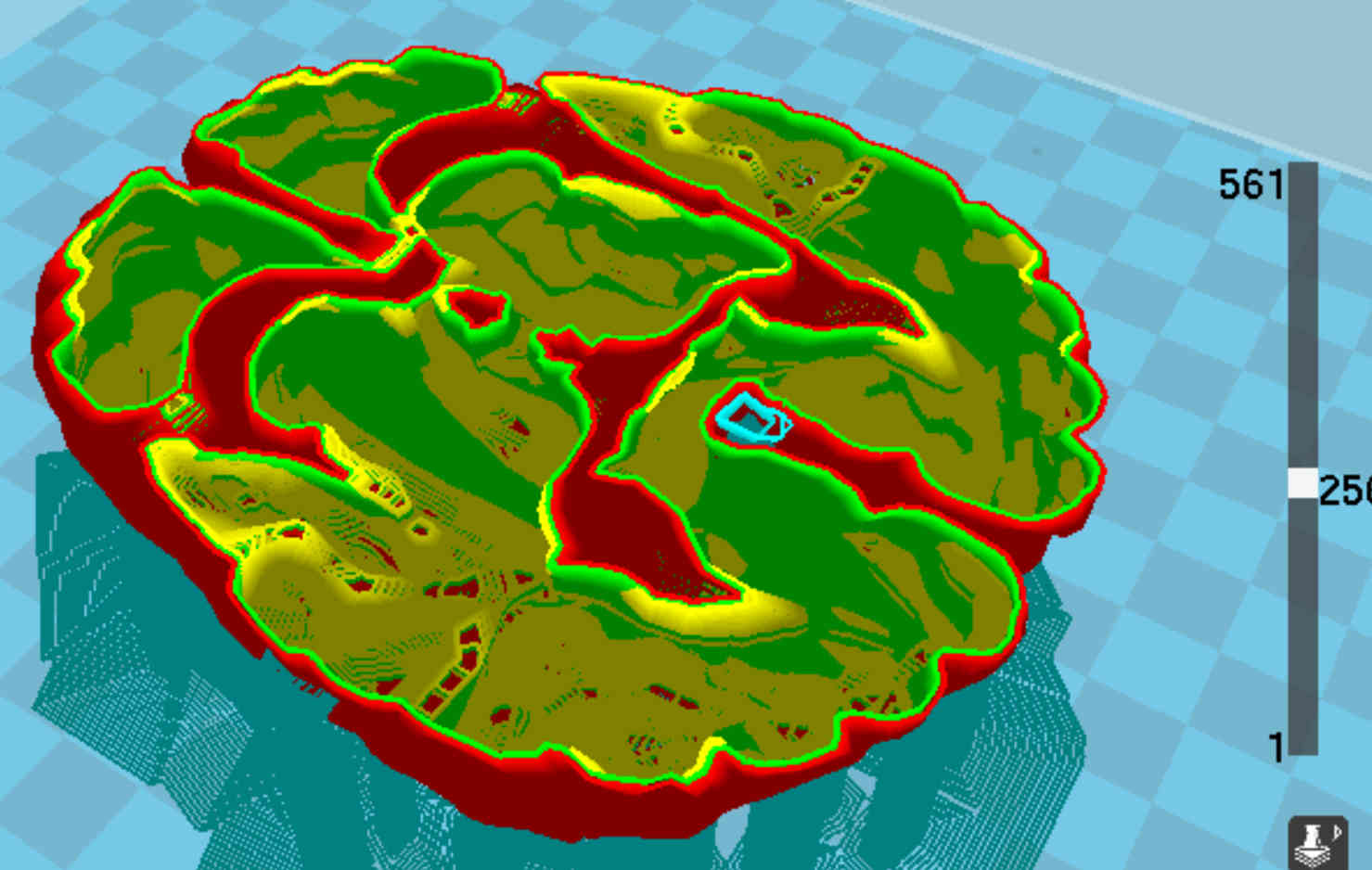
the orignal starting mesh is pathological for printing due to its internal structure
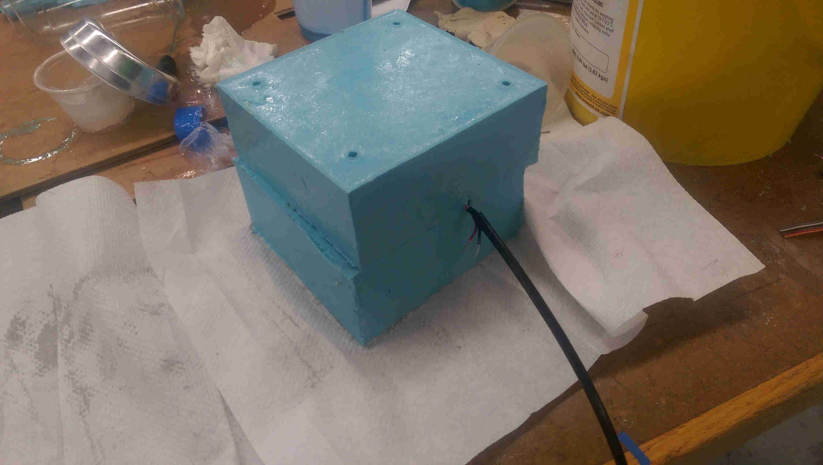
The workflow I used to contruct a physical brain was: 1. 3D print the brain 2. Create a 2-part oomoo mold for re-casting (2-parts to facilitating casting with embedded electronics) 3. Re-cast the brain in MoldStar silicone (with internal components)
I elected 3D print the original positive (rather than milling) due to the complicated topology of the brain (lots of overhangs, etc). The original .stl file used was rather pathological for printing due to its complex internal structure (for molding and casting, only the outside surface was important). I split the mesh in half in rhino (using the mesh split command in rhino) to print the two halfs (both had to be printed as one is the enantiomer of the other) and I also deleted some of the internal structure to speed up the prints.
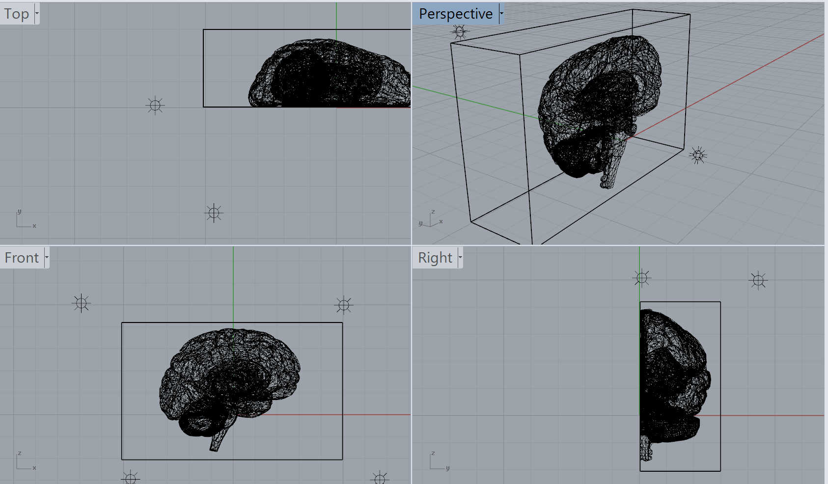
cleaned up rhino mesh
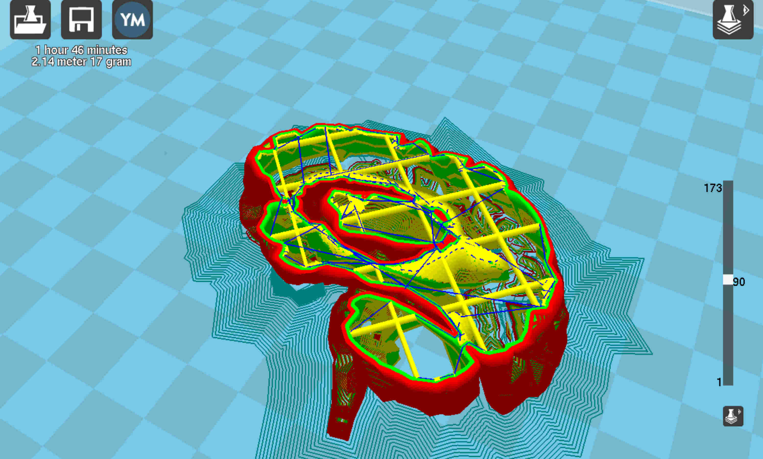
the cleanup up half-brain mesh, with a more sparse internal structure to speed printing
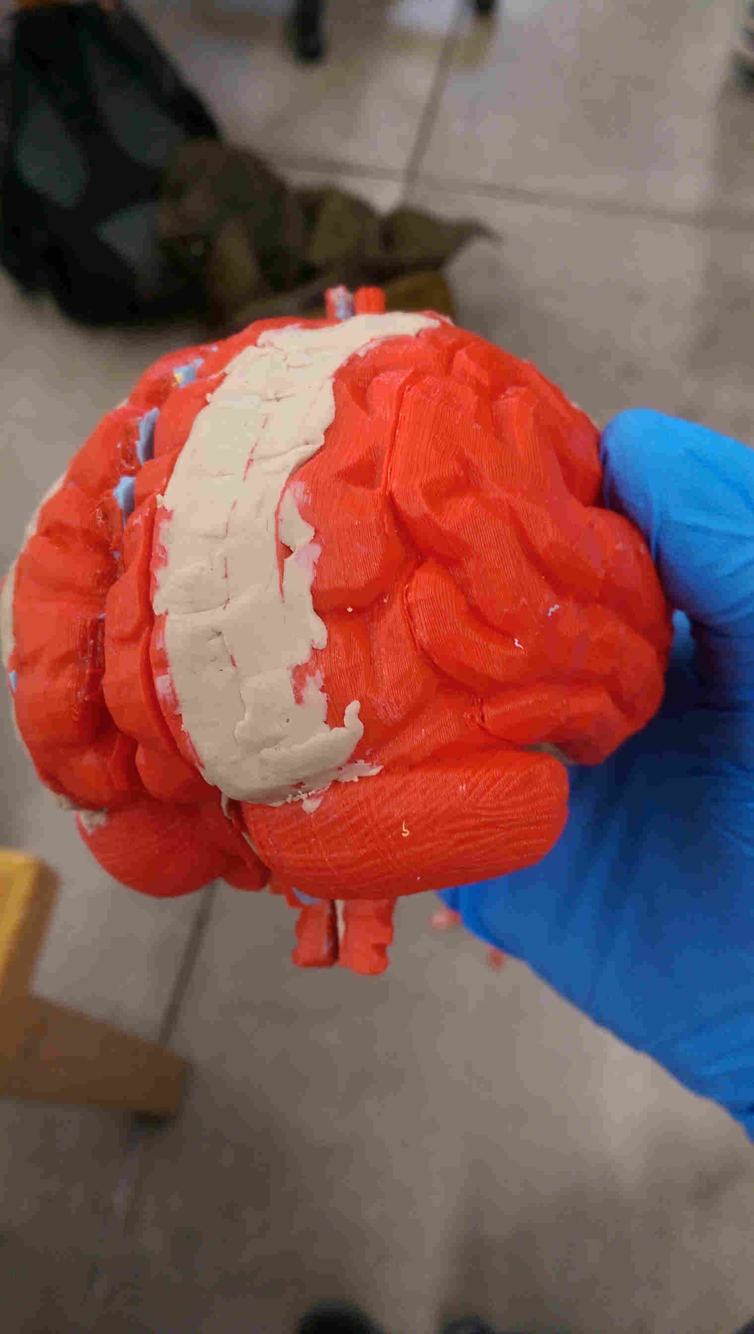
I printed each half of the model on an Ultimaker printer. Even with the cleaned up models, the prints were somewhat pathological (certain sections apparently didn't attach). But with some post-processing (addition of clay to patch up the holes), they were perfectly servicable for casting. After making both halfs of the mold, I tested the molds on a component-less silicone brain. It turned out very structurally sound, though very sticky to the touch on the outside, presumably due to an uncured outer layer (the possible culprit: expired MoldStar batch?). Washing with peanut butter seemed to clean up the uncured residue.
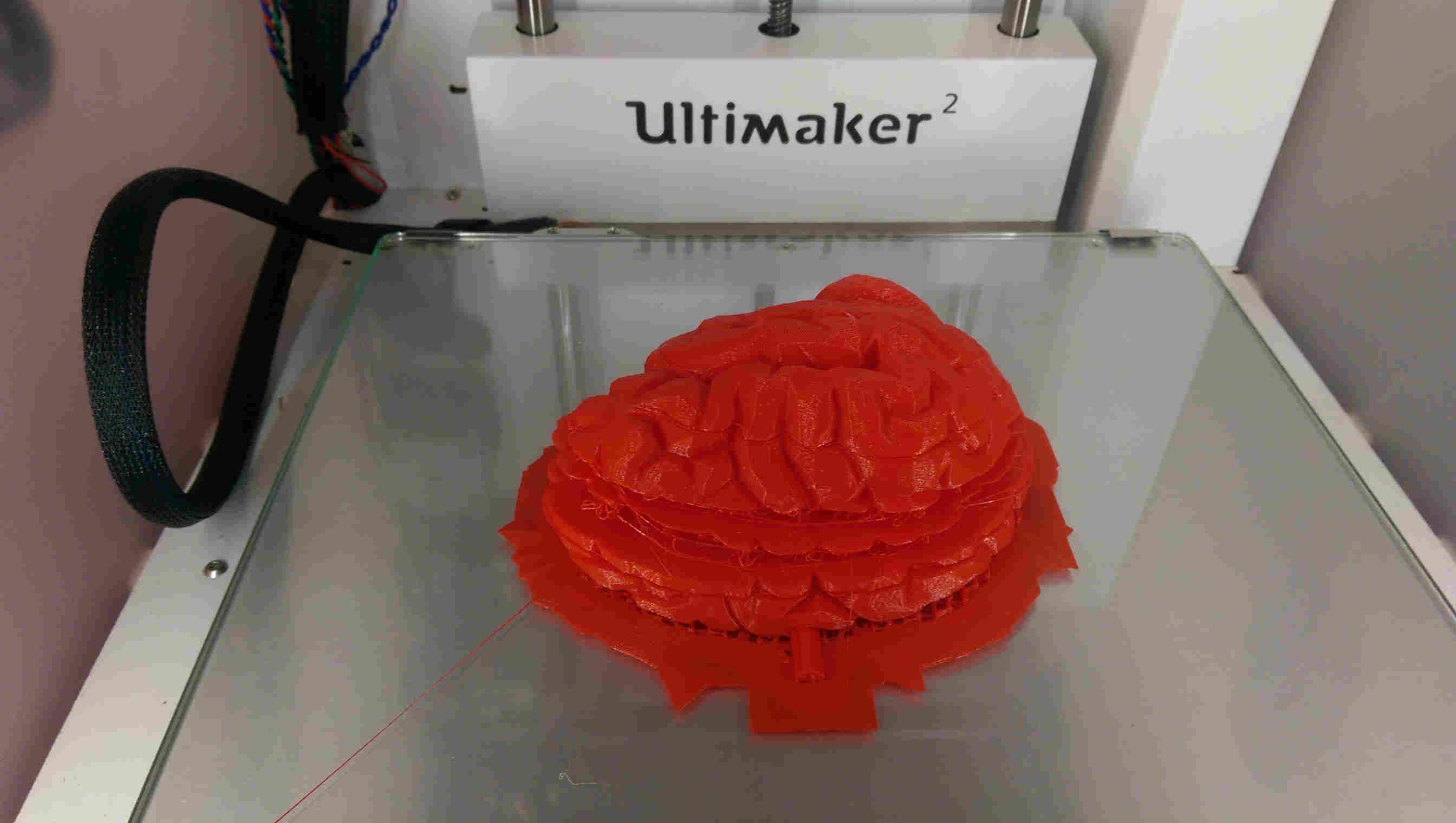
completed print - with several missing layers
with clay
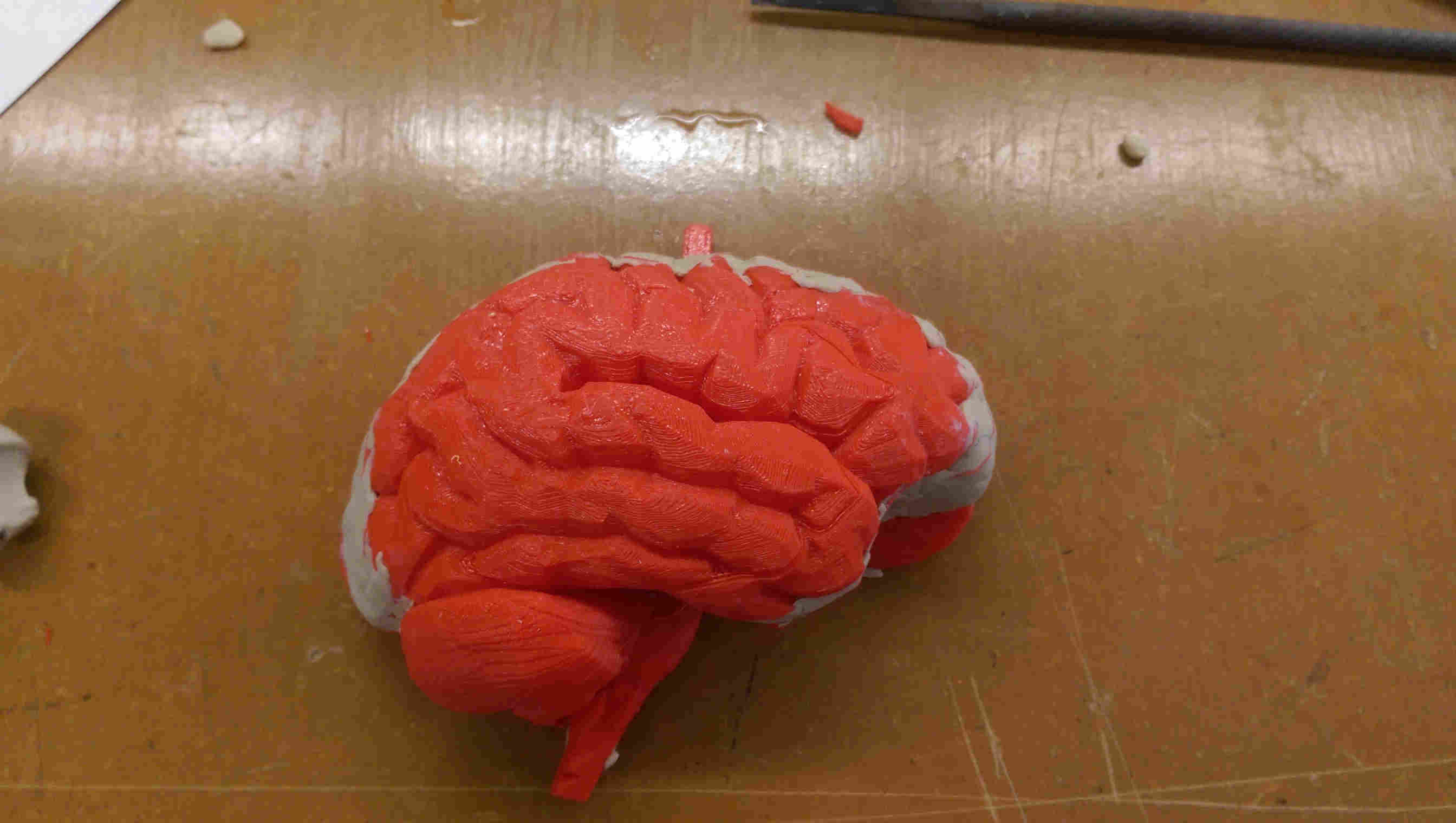
full brain print
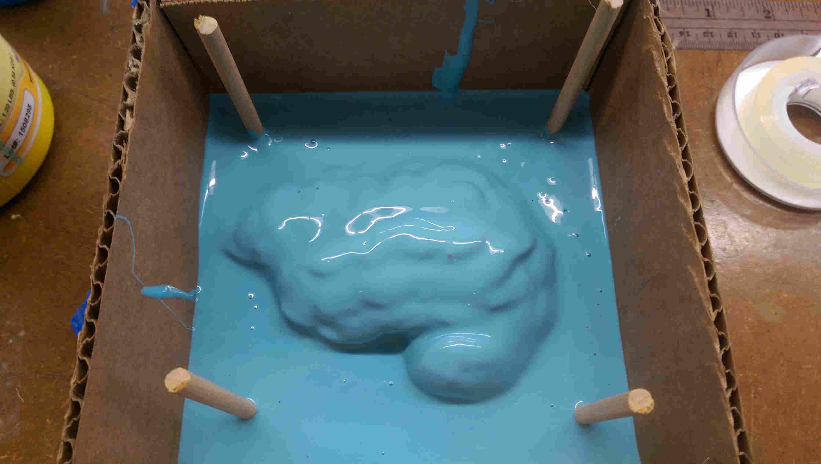
pouring the oomoo mold
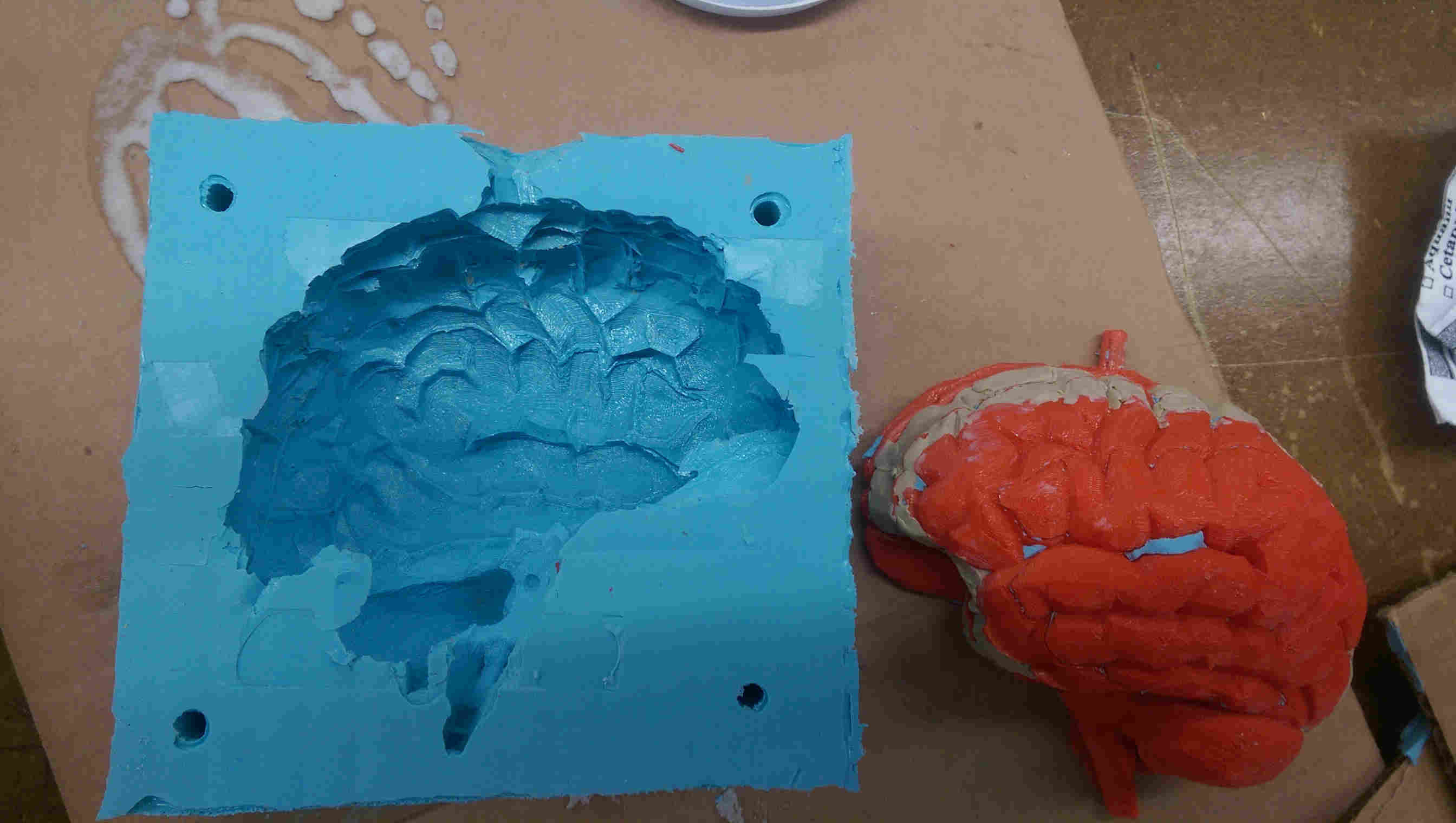
completed half-mold
both parts
rubber brain
input electronics
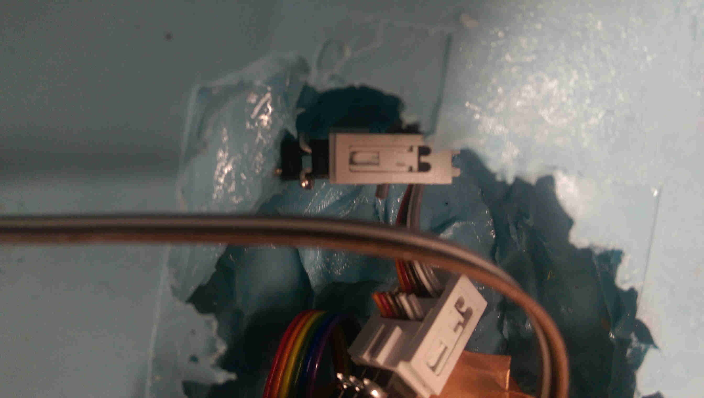
In parallel with developing the fabrication process, I decomposed the electronics into seperate input and output modules for debugging. For input, I decided to sense compression using transmit/receive modules (i.e., sampling the response of one copper pieces to a rising edge on a parallel piece). I first played around with Neil's hello world tx/rx board using plates embedded in silicon.
test sensor...
...with board attached
For my final design, I didn't want to sense the absolute step response, but rather a differential response. I adapted Neil's hello world code to create an adapted version that triggers when the step response changes between samples by a certain value (which can be calibrated depending on the sensor geometry).
I tested the revised version using Neil's Tkinter-based FDI interface, and founded that I could trigger the microcontroller response by squeezing the rubber module.
squeeze test
output electronics
I wanted the toy brain to either light up or, ideally, give some amusing audio output when poked. Adding LEDs is simple enough, but I wanted to debug higher quality audio output first before making the final electronics design.
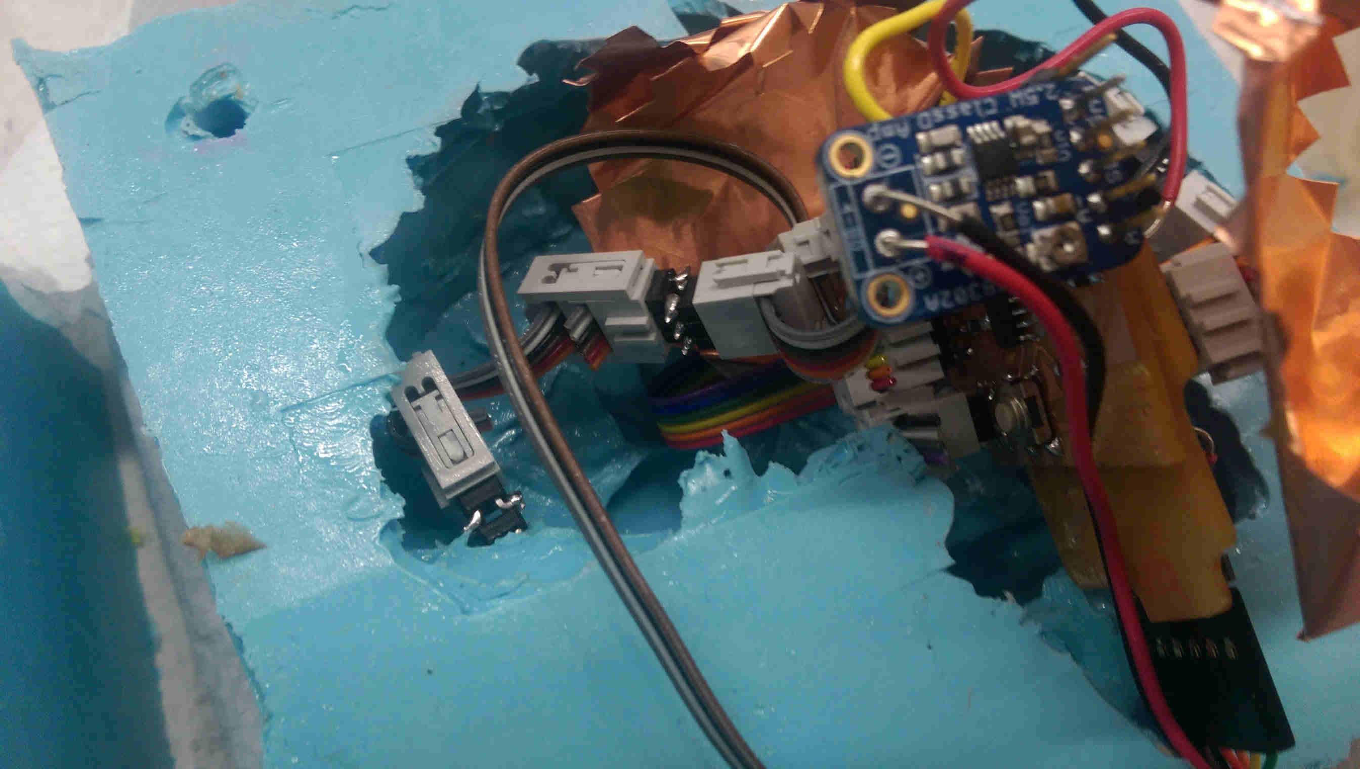
After my previous misadventures with non-function H-bridge audio boards (which I later realized was due to me trying to supply the H-bridges with 5 V; they require at least 8 V) I ordered a $3.95 class D audio amp component board (adafruit product ID 2130) along with a $2 speaker (adafruit product ID 1314) from adafruit for my project. The Amp board takes 5 input pins (audio +, audio -, ground, Vcc, and a shutdown pin that shuts off the amp when the pin goes *low* - I learned this last part the hard way after assuming the oppposite) which interfacing easily with FTDI-style surface mount headers.
my first iteration of the output board had the shutdown pin incorection, but nothing some post-processing couldn't fix
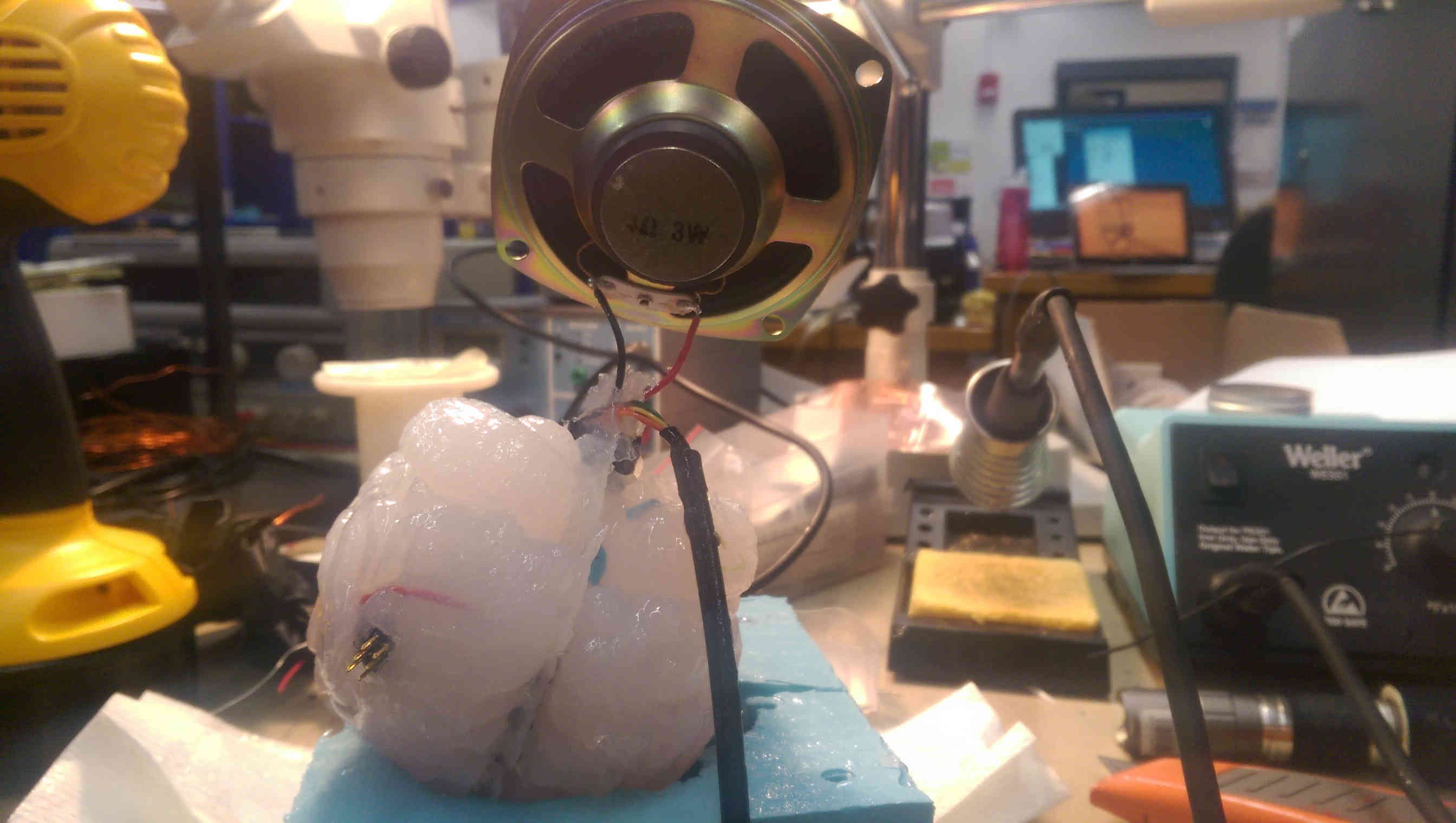
Fixing the shutdown pin yielded high quality audio output (I used frequency chirps to test) and at larger volume than the dinky lab speakers we had.
sound test
integrating electronics
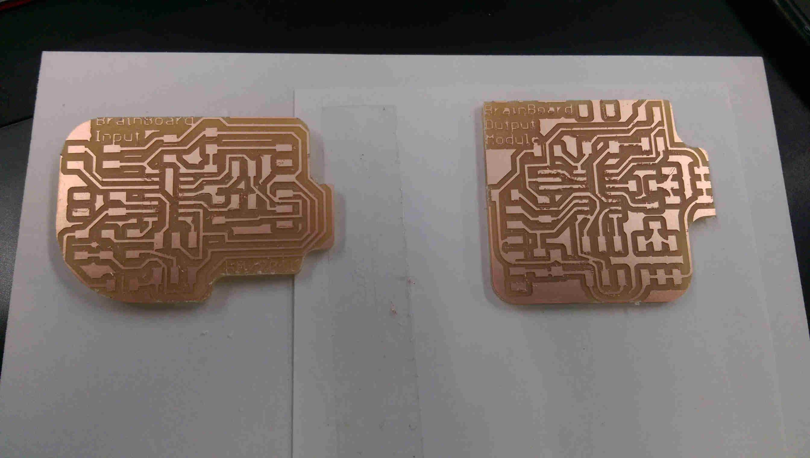
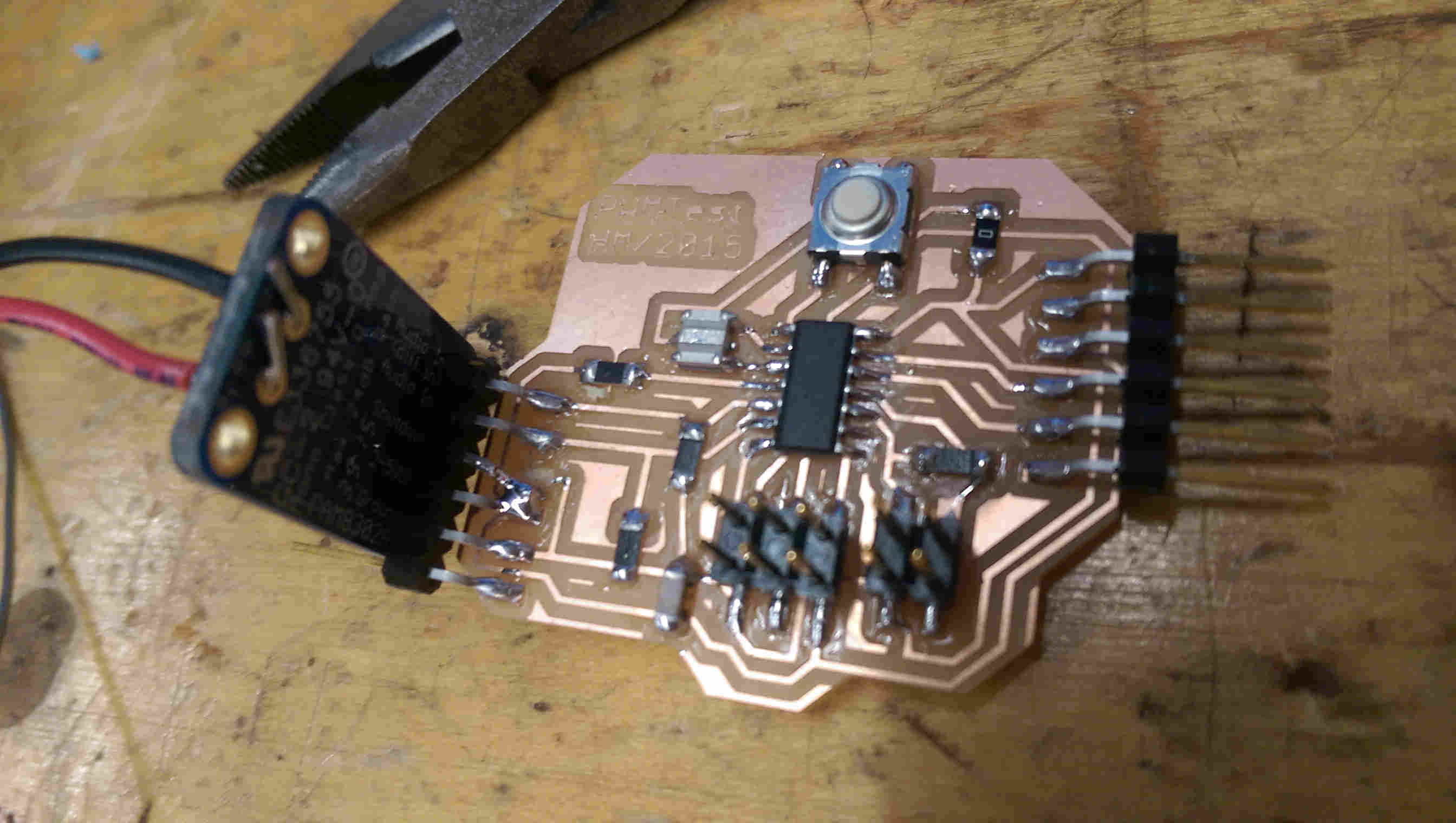
input and output boards, final design (before de-burring)
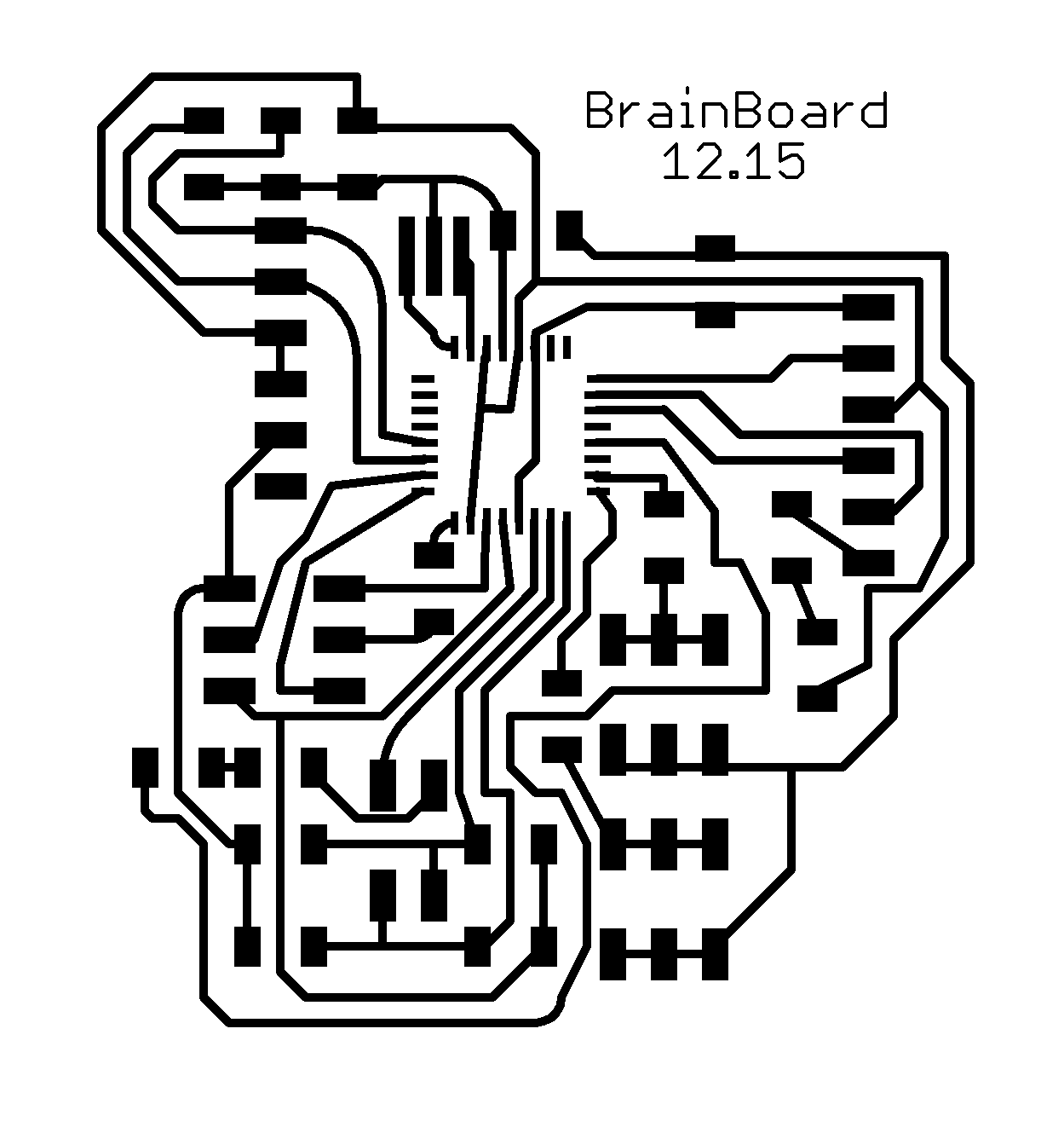
In order to integrate the electronics, I made 3 board designs: revised input/output boards for the TX/RX and audio output boards (this time with extra pinouts for LEDs on ribbon cables) each using ATTiny44's, as well as a single integrated board using the ATmega328. For a lower risk first iteration, I went with the two ATtiny44 boards (as I am more familiar with programming them). My design was to have the input board powered through an FTDI (useful for calibrating the TX/RX modules once they're embedded in the brain rubber) and to power the output board using a ribbon cable from the input board (containing 4 pins: 1 GND, 1 VCC, and 2 triggers for the two TX/RX modules).
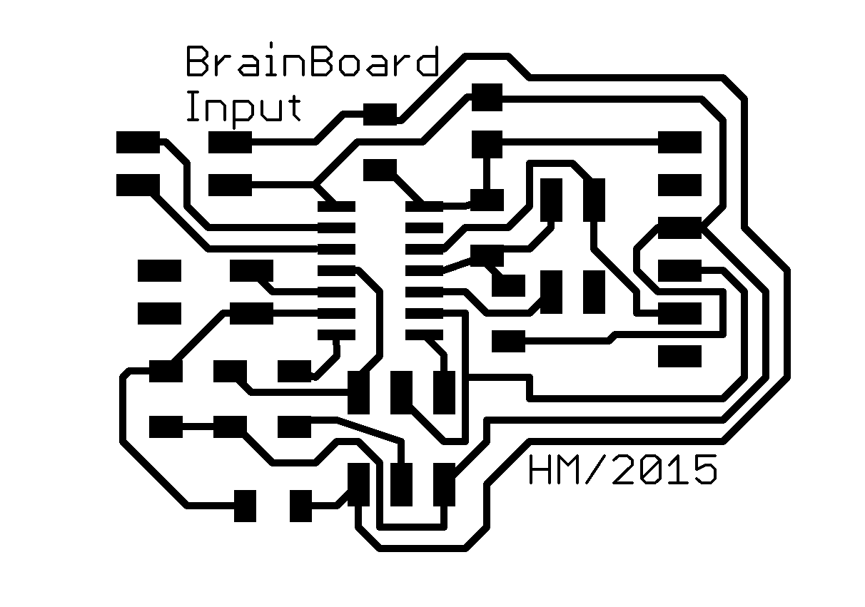
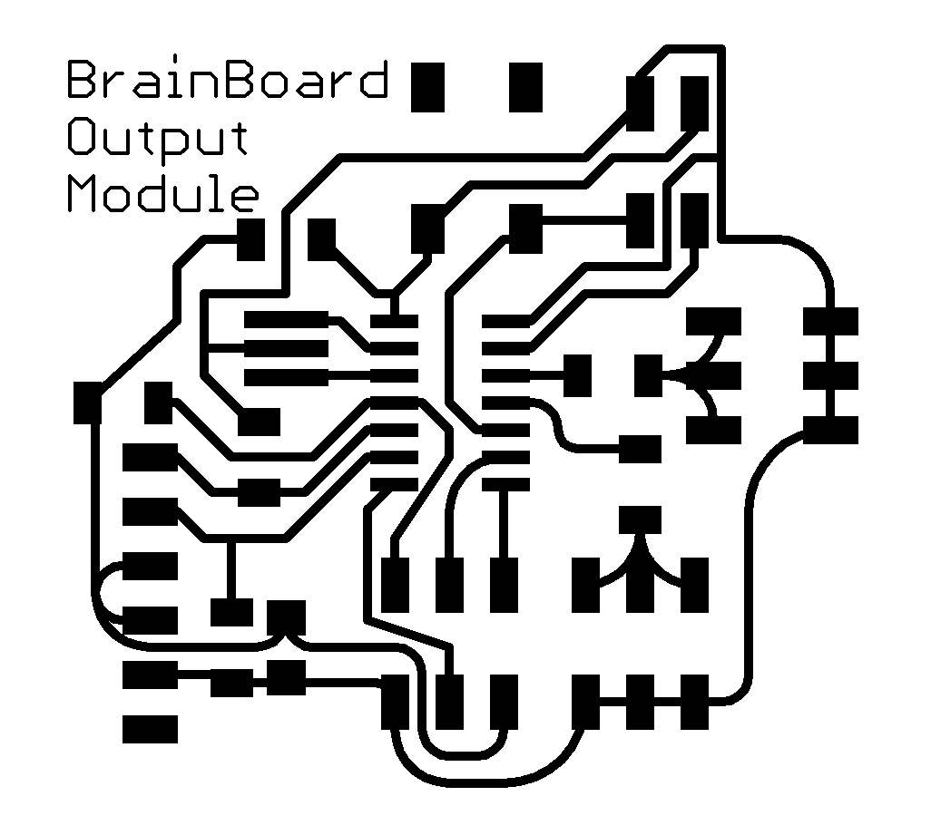
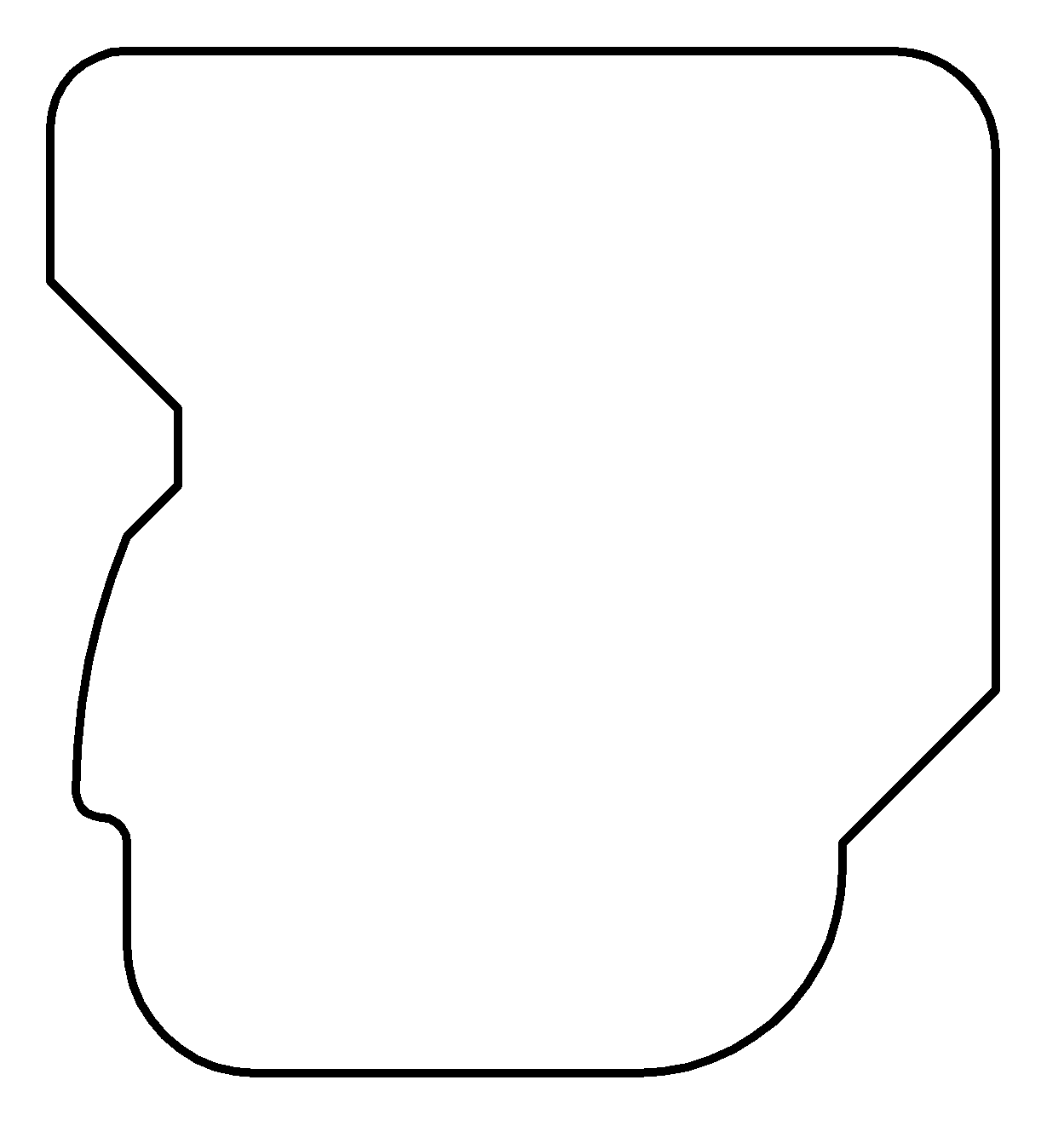
The input board is here (outline) and the output board is here (outline). (the Atmega design is here, with outline).
I first debugged comms between the input and output boards using the test 'squeeze' module. I turned off the audio output (to minimize annoyance) and used 3 LEDs to visualize and confirm triggering on each of the TX/RX pinouts. One pinout was much more sensitive than the other (perhaps due to the leads being more spatial separated) but both worked fine.
I/O test
sound test
The final code for the
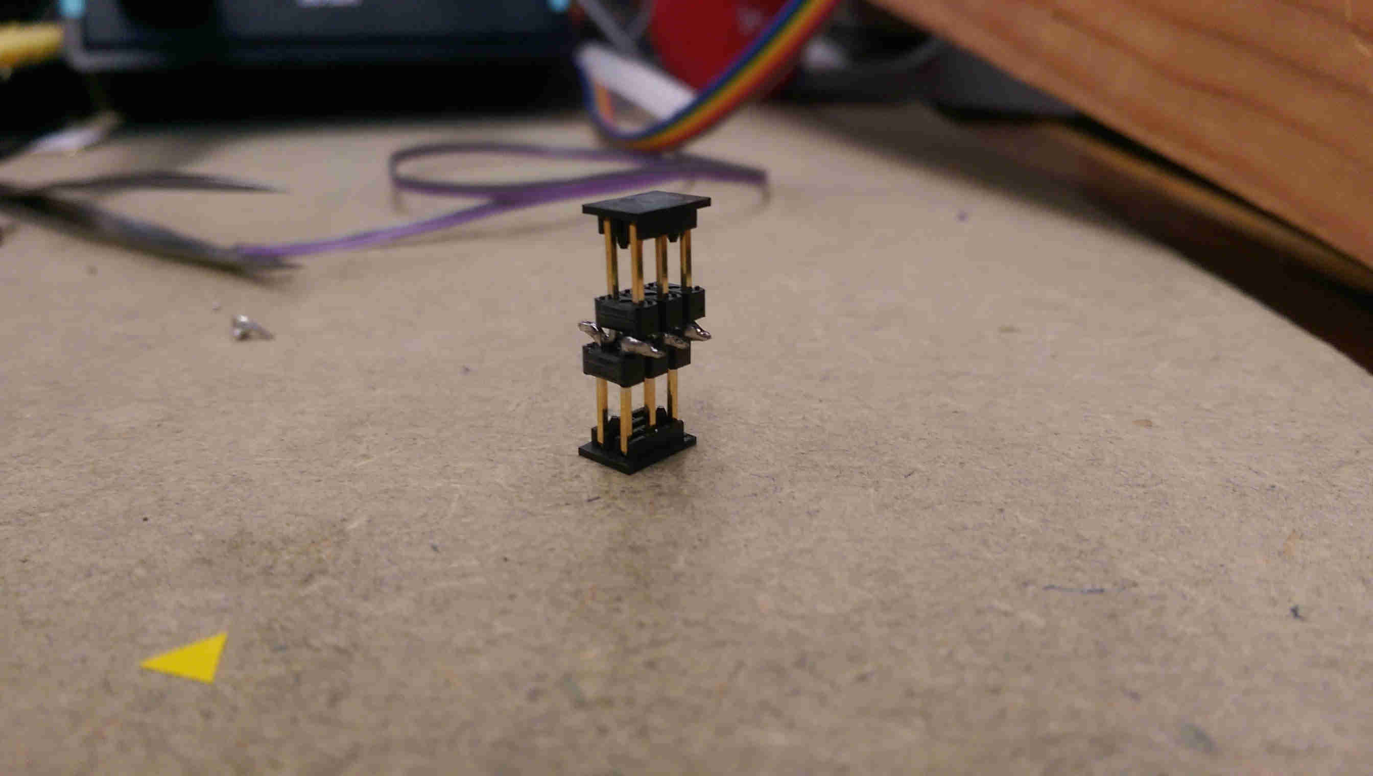
a hack so that the ISP headers for the modules can protrode from the brain surface, making the modules re-programmable (and calibrate-able) after embedding
brain fab
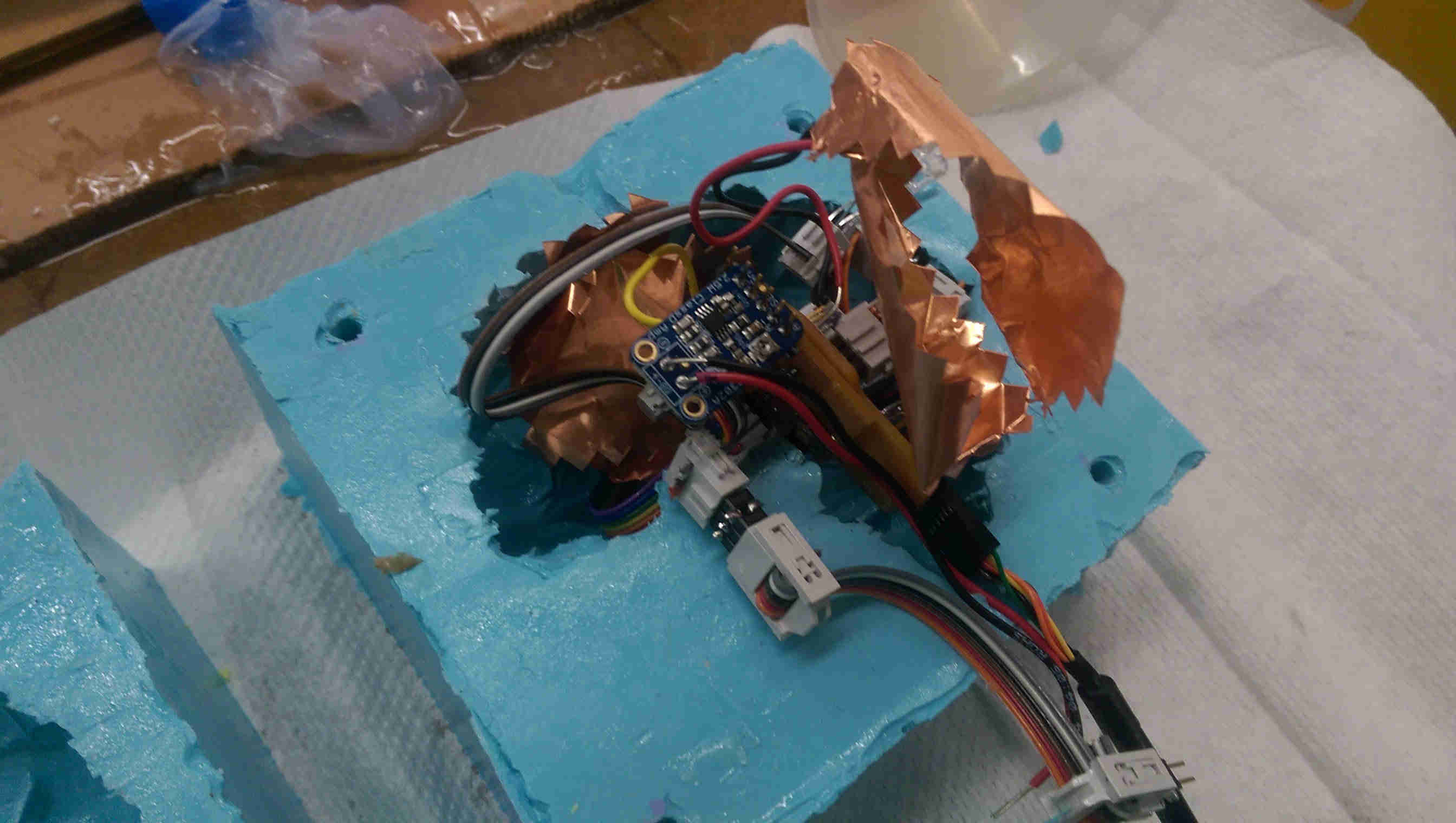
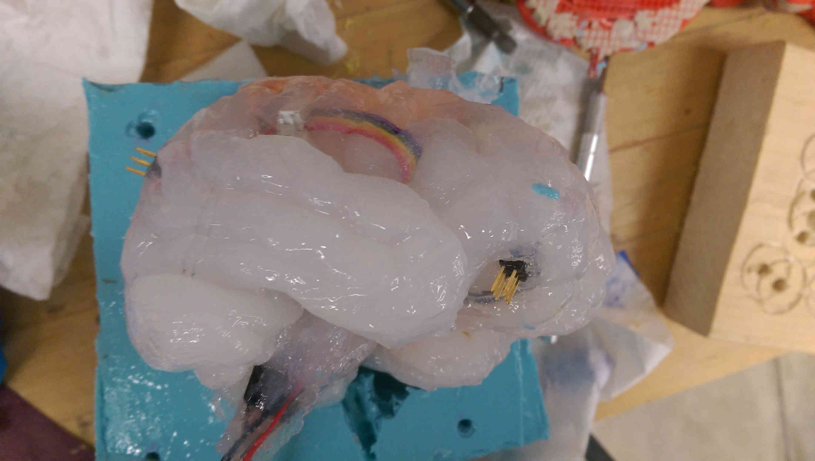
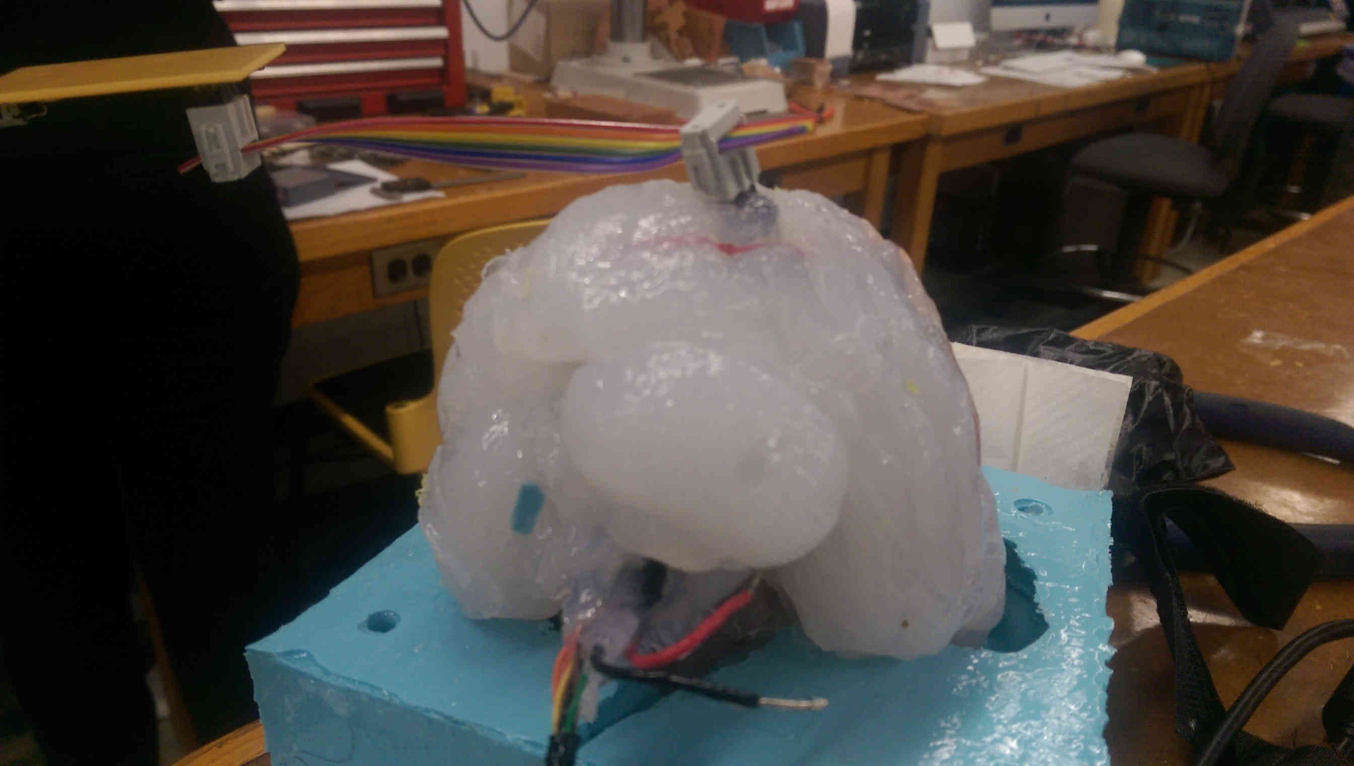
The last step involved casting all of the electronics in a MoldStar silicone brain. It ended up being quite a close-packed configuration, what with the 2 sensior modules, 2 ribbon cables for LEDs, the FTDI interface, the audio speaker leads, and the ribbon cables connecting the boards. Still, it all *just* managed to fit.
stuffing my brain
pushing the ISP headers into the oomoo mold left them accessible after the mold had set
everything in its right place
Unfortunately the MoldStar mix was uncooperatively viscous, and did not pass easily down the entrance hold I'd left at the top of the mold. Instead, I didn things the less robust way - I carefully poured the mix in the one half in which I set the componentns, then threw some extra in the other and smushed them together.
Perhaps surprisingly, this actually worked alright. The first attempted at casting came out mostly looking great (with one hemisphere perfectly set - the other had suffered some brain damage), with the ISP headers, FTDI cable, and audio leads all accessible. I recast the other half again with more MoldStar mix to fill out the structure.
casting the brain
the bottom side of the cast turned out nicely...
... but the other side didn't set completely
brain damage
resetting the unfinished half of the brain
a fully formed brain, with internal components
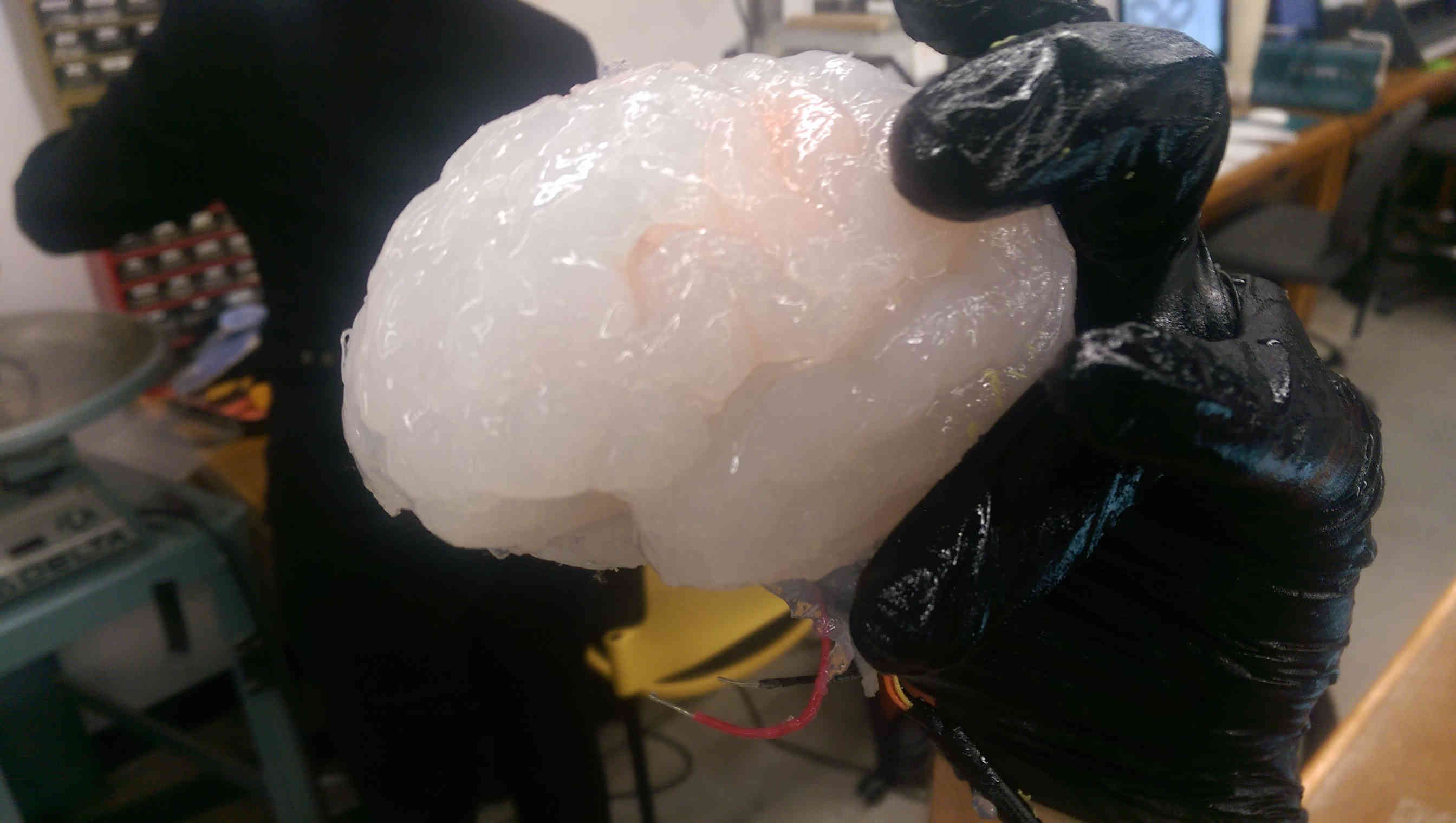
the formerly decayed side now is nicely finished
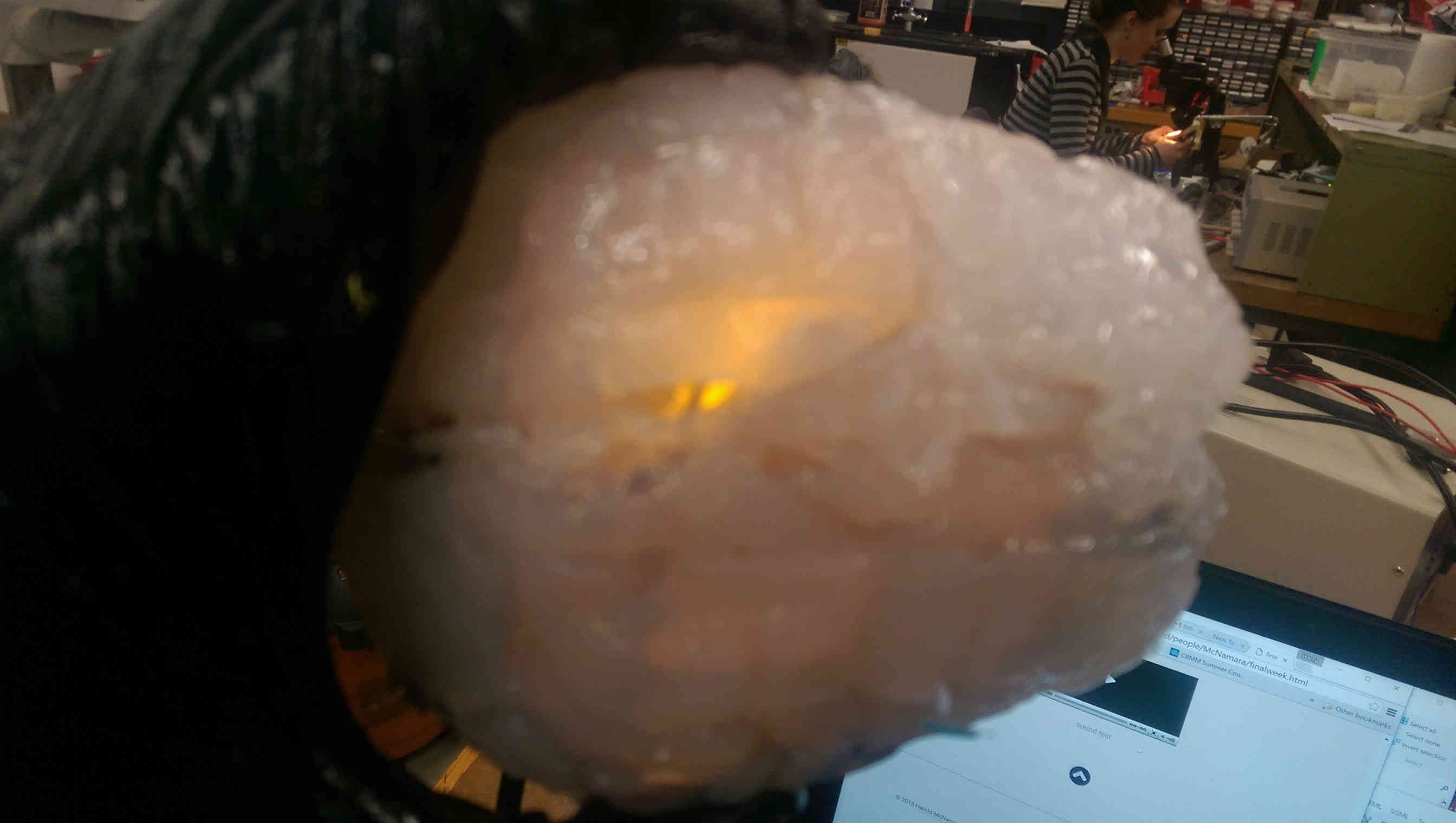
the internal yellow LEDs are visible through the silicone
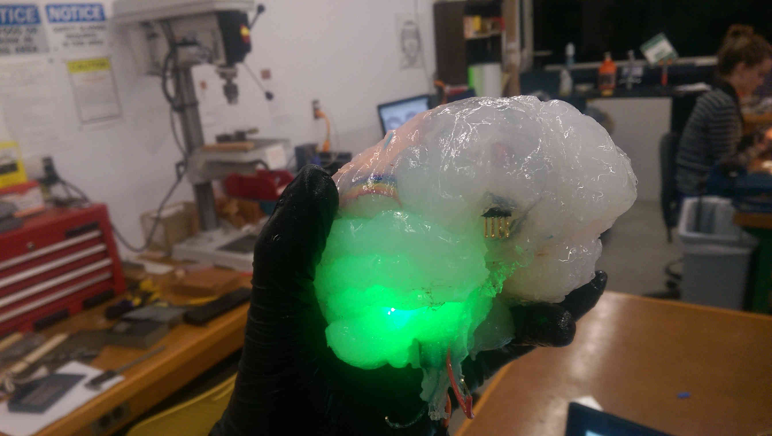
and the green LEDs
Casting the MoldStar in an OOMOO mold left a sticky finish on the brain of uncured mix. This also happened with the component-less test brain and the squeeze test module; each of these casts cured eventually over the next few days (in any case, the stickiness only makes the brain appear more physiological).
Because of the external accessibility of the ISP headers, the input and output modules can be reprogrammed (and in particular, input activation thresholds can be calibrated). Due to the admittedly random nature in which the components where set, it took some fiddling to figure out how to squeeze the brain to trigger the two output responses. There is a lot of cross-talk, and the output modules themselves (LED and audio leads) can trigger step responses in the TX/RX modules. Depending on TX/RX calibration settings, this can lead to cascades of responses, and even apparently spontaneous activity. These stochastic dynamics aren't unlike the dynamics of a real brain, and so I interpret them as a feature rather than a bug.
interfacing with the brain input module with the fab ISP
re-attaching the speaker
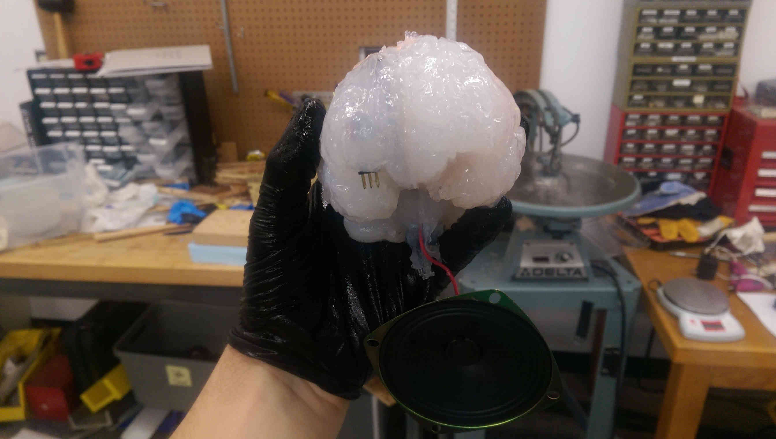
brainz
summary / recap
In sum, I fabricated and got working a prototype version of an interactive brain, useable either for amusement or for instructional purposes. The skills involved included basic design (the .stl model was not original, but had to be heavily edited; moreover arranging the intenral components and external FTDI+ISP interfaces required design elements), additive manufacturing (3D printing), molding(OOMOO) and casting(MoldStar), as well as non-trivial input and output electronics.
The function I encoded is simple (espcially the audio; the speaker and amp quality are sufficient to drive much higher quality audio than the simple chirps I used). The external ISP access especially makes the system easy to reprogram. A next spiral of development could either augment the audio output, or could involve more careful layout of components internal to the brain (or, given more time, just use a bigger brain!). I also designed a single ATmega board to handle all I/O, which would also be worth developing.
Bill of materials:
- Pint kit OOMOO 25 (Smooth-On) ($30, 1 time expenditure)
- 1/2 Pint kit MoldStar (SMooth-On) (~$15 / brain)
- Ultimaker filament for 3D print ($???, 1 time expenditure)
- 2x PCB stock
- 2x ATTiny44 uC
- assorted eletronic components (resisters, headers, etc)
- 3 W, 4 Ohm speaker (adafruit) ($2)
- Class D audo amp (2.7 W) (adaruit) ($4)