week 7: embedded programming
Our charge this week was to program a PCB to do something. I decided to design and program an adapted version of the 'hello world' board to generate an analog triangle wave output.
board design
While I understand that the some of the attiny44 pins have a PWM output mode that could be adapted to this function, I hard-coded a PWM routine on one of the unutilized pins on the 'hello world' board. I also configured the board such that output could be connected to a basic passive RC low-pass filter to smooth out the waveform, and a green LED to aid in visualizing output.
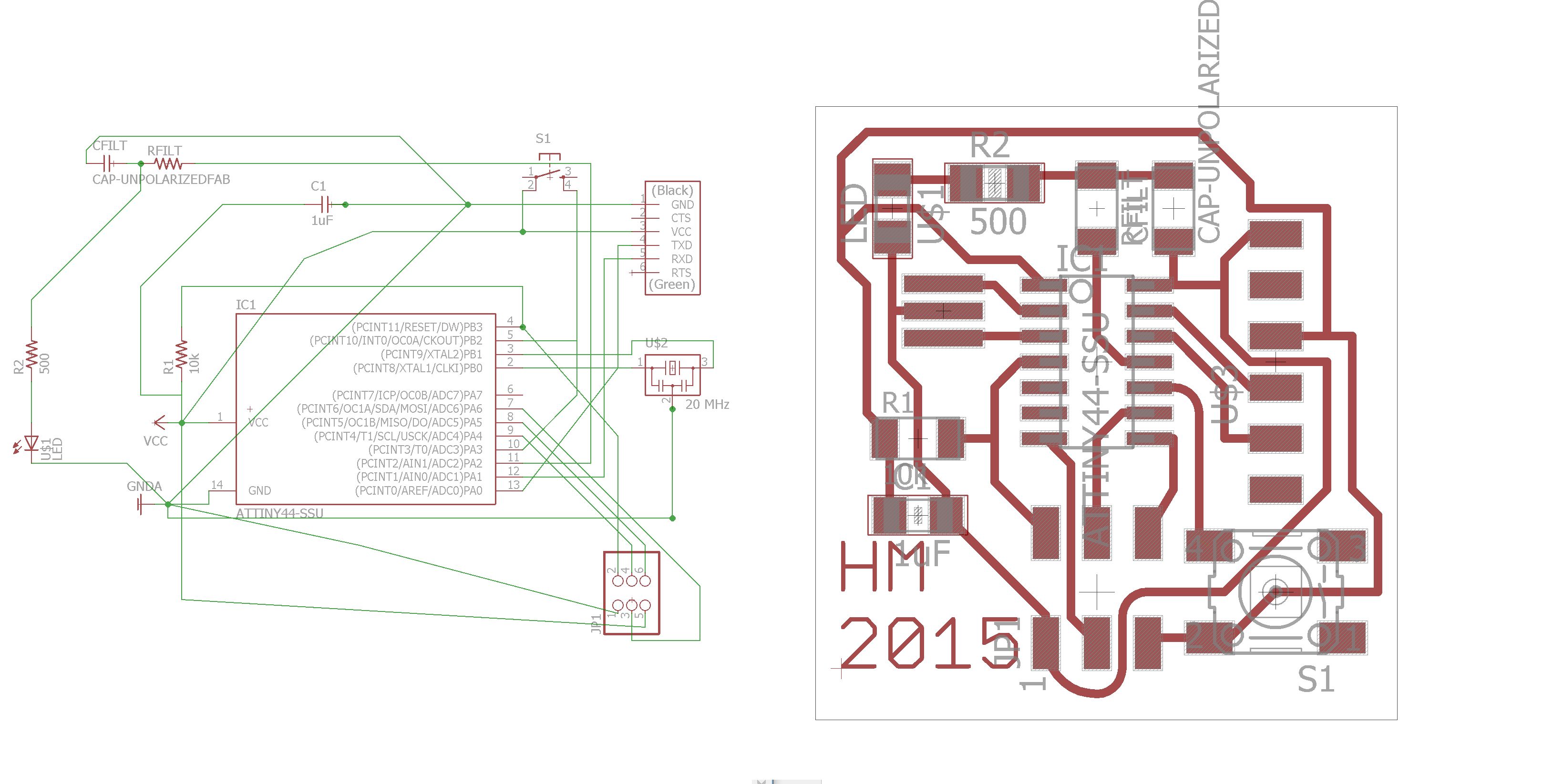
board design in eagle
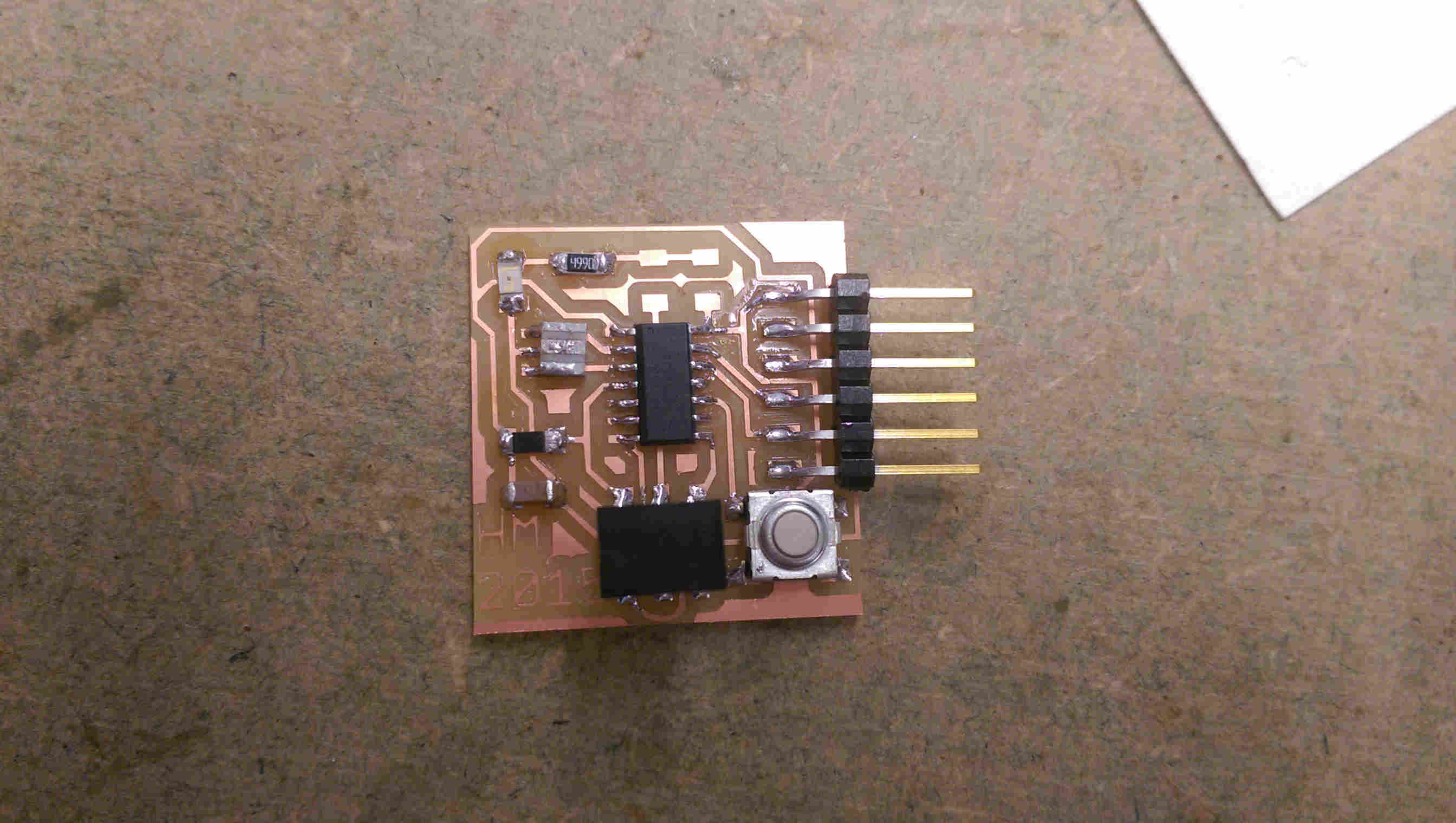
fabricated board, before adding filter components
programming
After fighting a bit with getting to get my C code to compile in the cygwin shell (on windows), I opted to install the arduino IDE and develop my code therein.
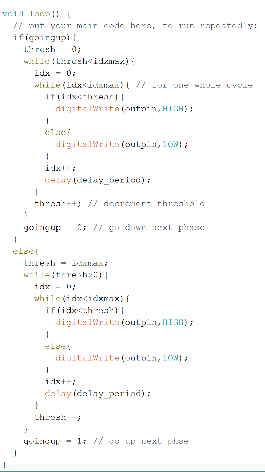
first iteration of triangle wave dac code
To get the program to load properly, I had first had to: 1. install the ATTiny board settings 2. install the usbtiny driver for the fabISP 3. select the appropriate microchip (ATTiny), board (ATTiny44), clock (20MHz external), and programm (usbtinyISP) 4. burn the bootloader The system was thus configured to upload programs to my board via the fabISP.
The first version of the program effectively placed a 'triangle wave' PWM effectively. I also added a 0 Ohm resister to visualize the output on a green LED.
blinking LED
PWM oscilloscope output
I then added a simply passive RC filter to smooth out the PWM cycle to create an analog signal. There are two time scales in this program: the shorter, pulse width modulation, and the longer triangle wave period - we want to smooth the former while preserving the latter. I also noticed that the period of the cycle was very slow (so slow that you could visually see the LED blinking. I speculated that this was due to a high usage of conditional value comparison statements. I reframed the code to use microsend delays instead, and added the filter components. The resulting singal looked substantially more trianglular, with frequency ~ 1 kHz.
first attempt at filtering the triangle wave (with the initial code)
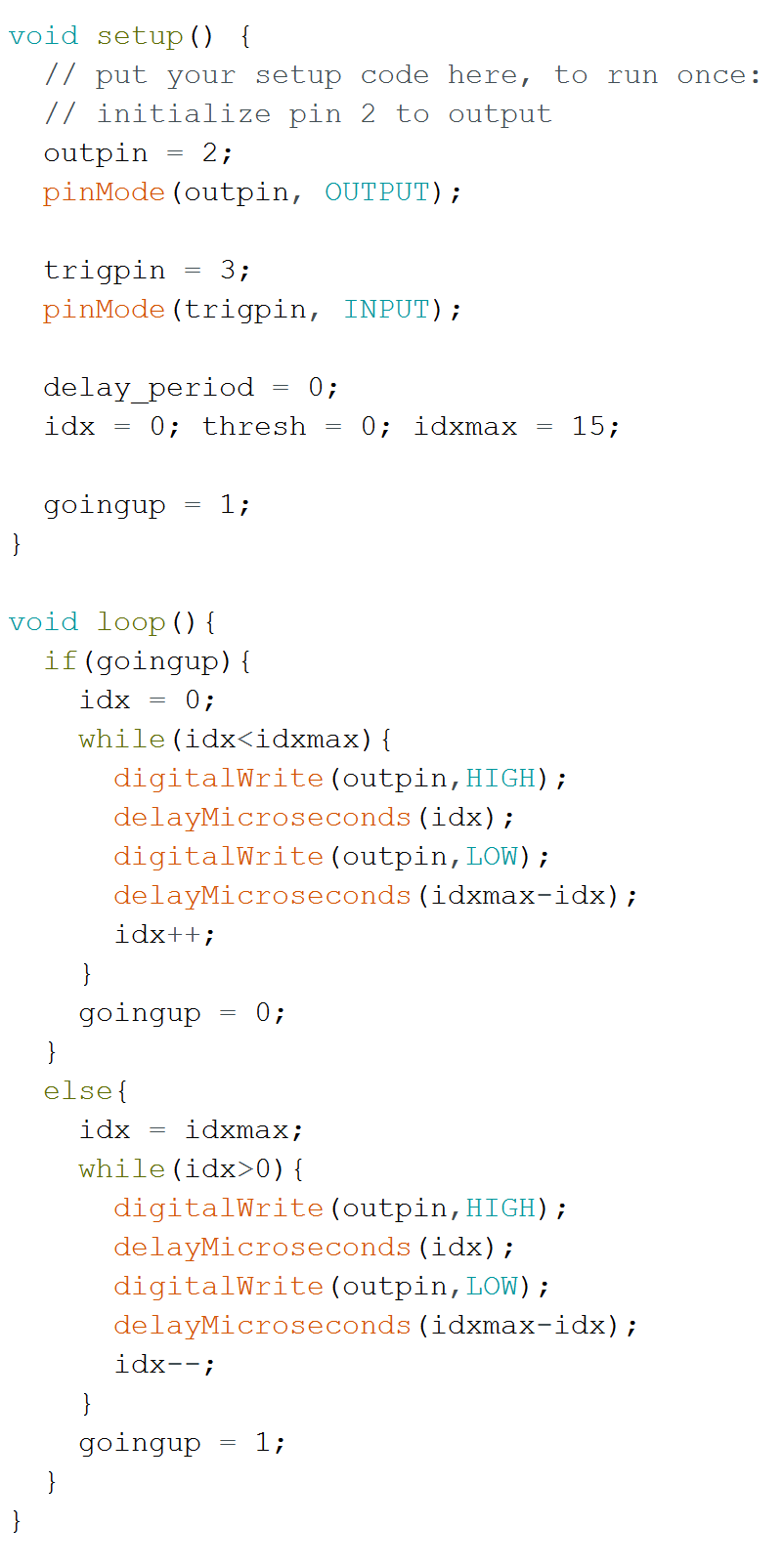
revampled code
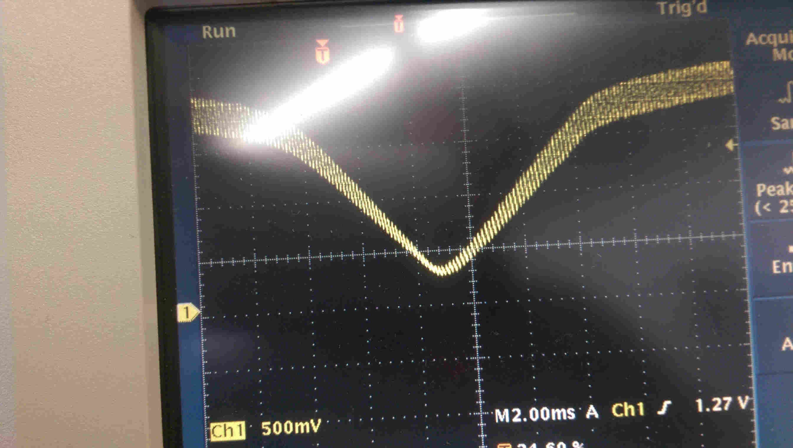
triangle wave with r_filt = 500 Ohm, c_filt = 10 uF. f~1kHz
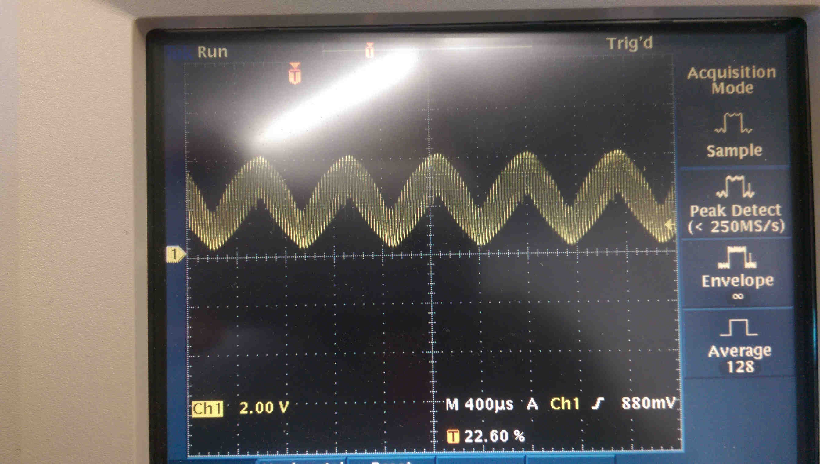
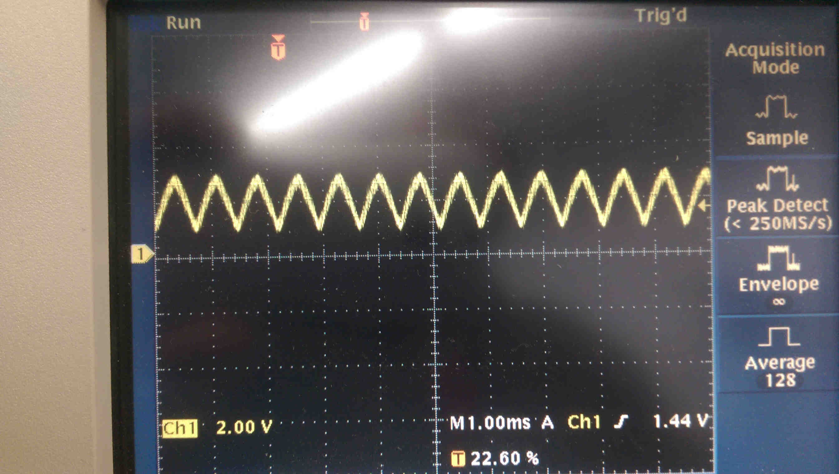
rescaled triangle wave - showing that the high frequency compoent
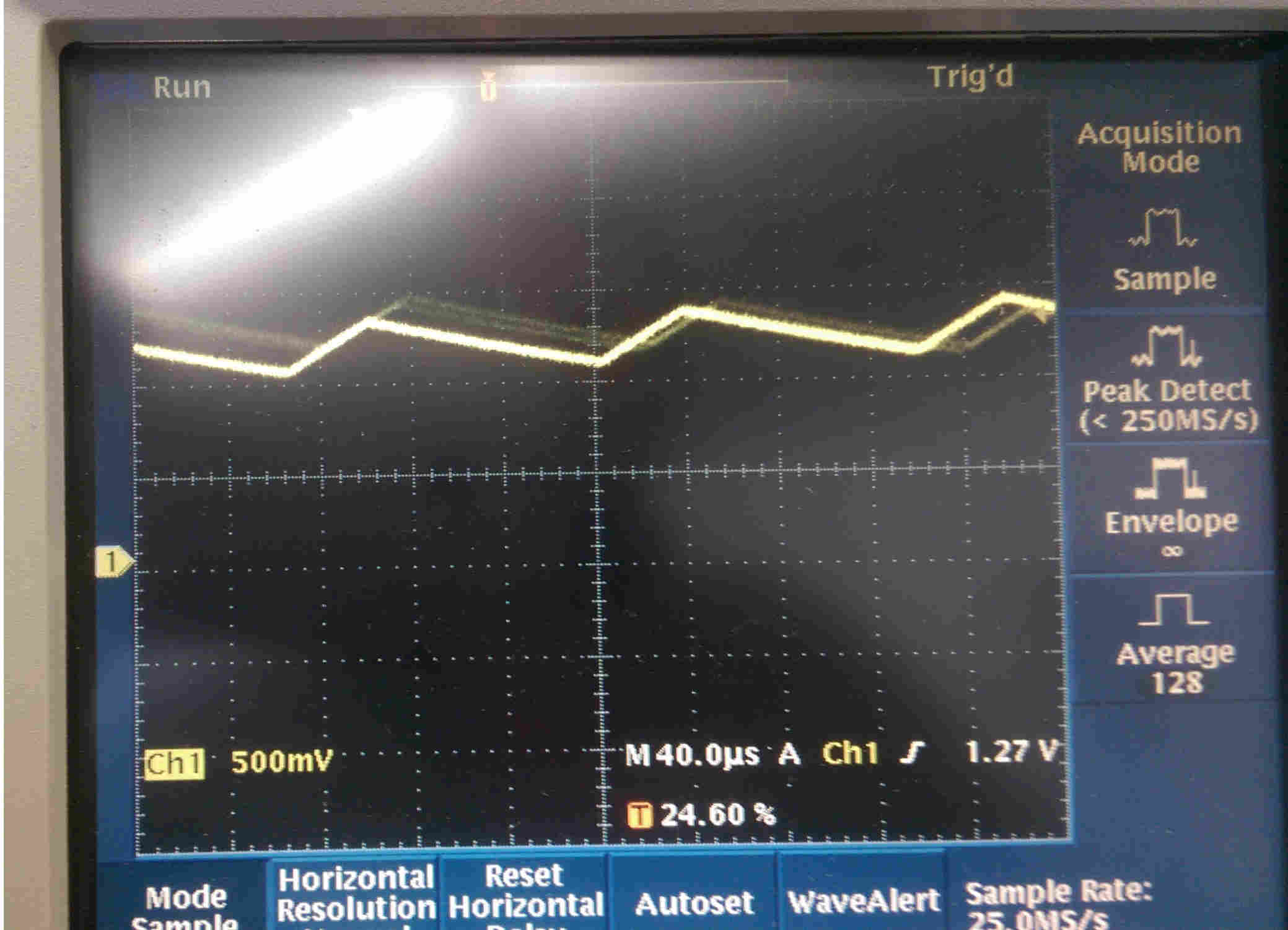
the high frequency component, zoomed in
Next steps in develop could include: using the tacticle switch to trigger interrupts that change the signal mode (e.g., from triangle to sawtooth, square waves, sinusoids, etc.) and using FTDI communication to allow a user to dynamically set the wave period.