week 8: output devices
This week, I designed a board to use the built-in PWM output on the ATTiny44 to send a frequency-swept chirp signal to an audio speaker.
first board design
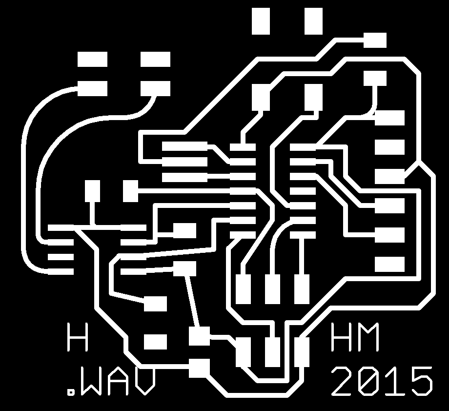
My first board designed used two pins on the ATTiny44 with built-in PWM modes (i.e. PB2 and PA7) to drive either of two pinouts connected to the speaker, each current-sourced seperately with N-type MOSFETs. The idea was to be able to drive current either way through the speaker (analogous to using an H-bridge), but it ended up not working (the board design relied on being able to set either of the pins to 5 volts through the MOSFETs, which, in my hands, seemed not to work).
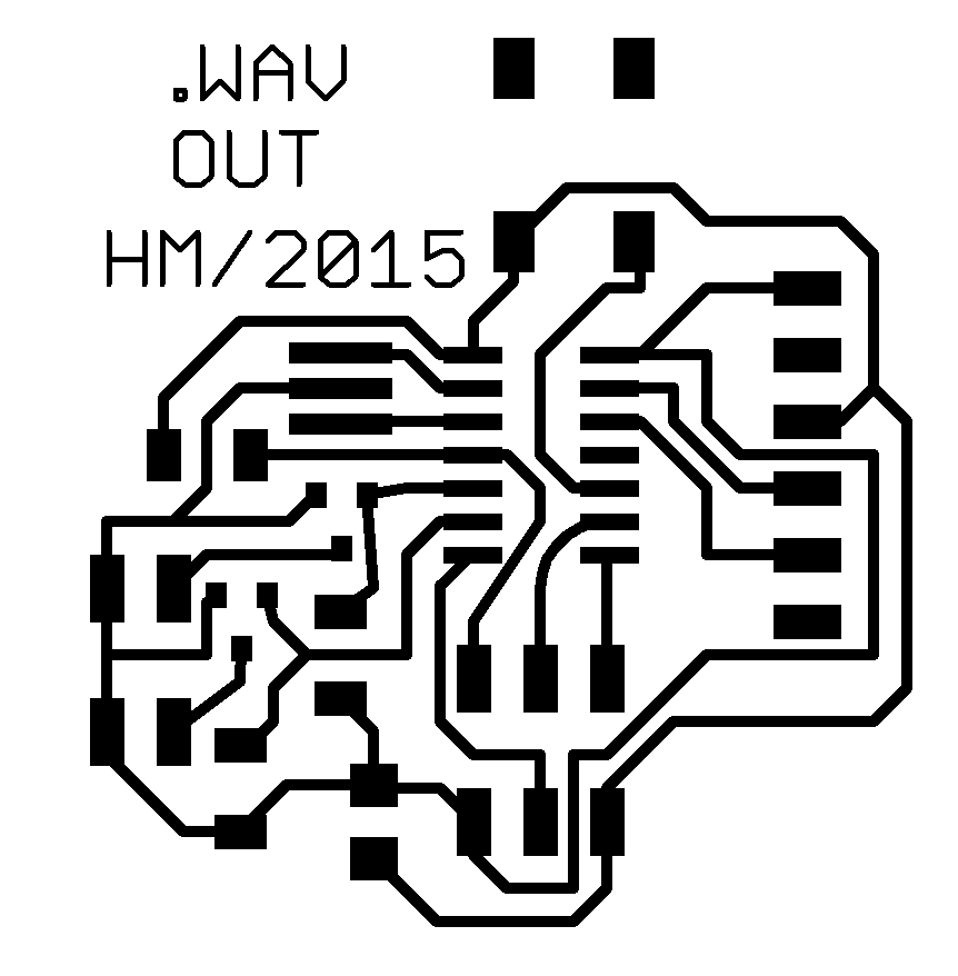
board design in eagle
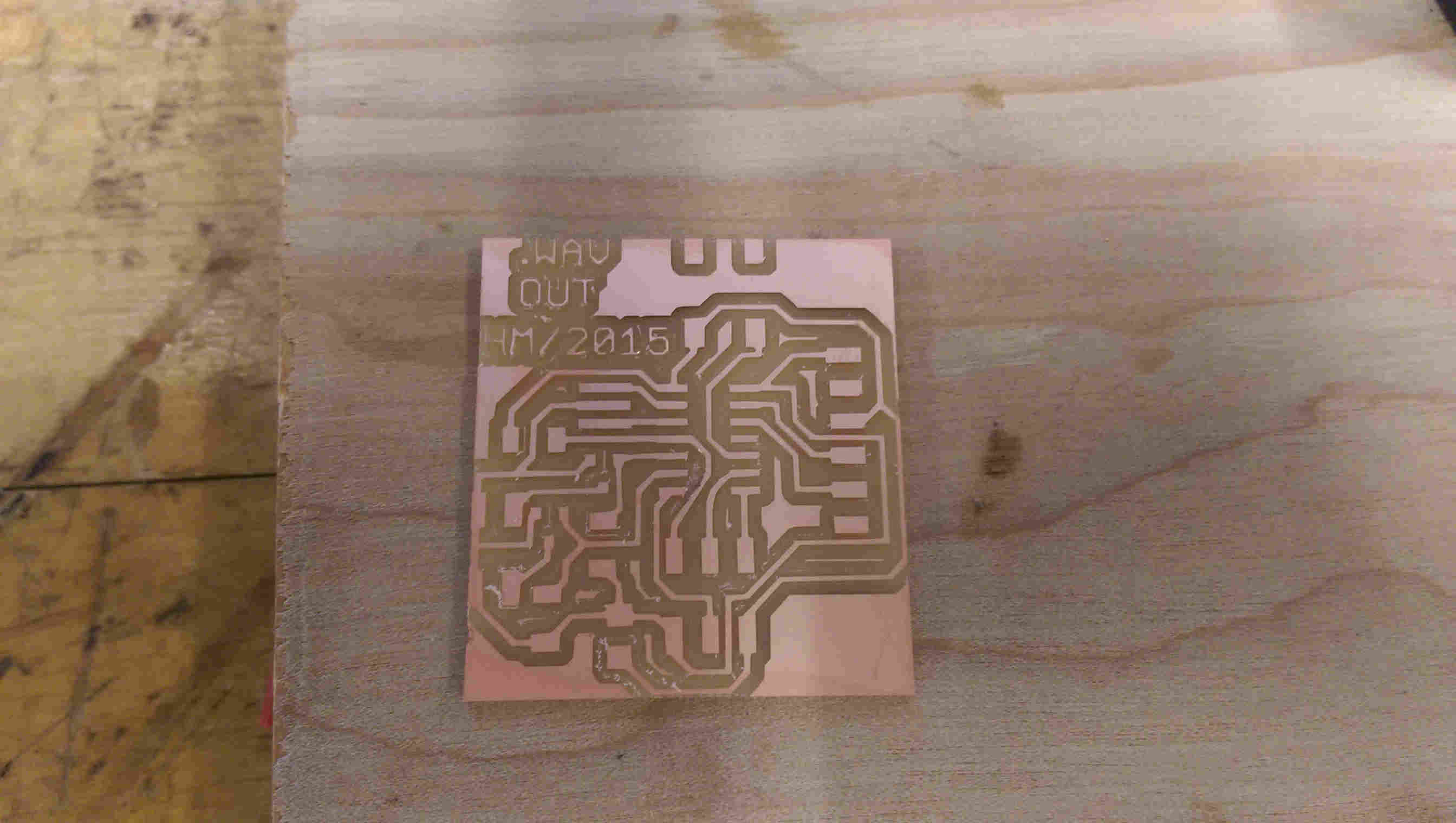
milled board, before stuffing
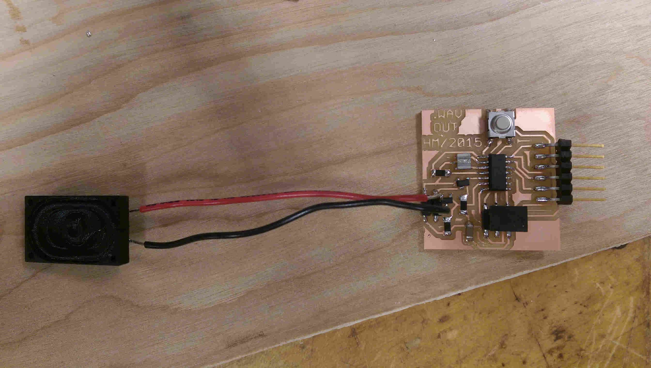
with components added
Debugging the hardware PWM mode took some fiddling, but I eventually code the code working correctly. The PWM mode works by comparing the 8-bit clock register to a threshold value. So, if the threshold OCR0A register is set to 0x80 (=128), then the PWM pinout will have a 50% duty cycle (as the counter counts to 0xFF = 255).
Page 74 of the ATTiny44 datasheet details how to set the PWM waveform mode registers WMGO0:2. E.g., the registers can be set to use OCR0A register as the maximum value for the OCR0B counter to achieve shorter intervals of PWM. In order to properly configure PWM mode, the registers you need to set are: 1. The clock prescaler register CLKPR 2. The clock divider in TCCR0B 3. The waveform generation mode register (WGMO0:2), contained in the TCCR0A and TCCR0B registers
I compiled my C code in the arduino IDE (borrowing only the arduino 'delayMicroseconds()' function, as _delay_us() requires a compile-time integer value, and I wanted to loop over different delay lenghts).
I debugged the code by checking the pin output on the oscilloscope, and realized that the original board design wasn't going to work (using N-type MOSFETs to source current, when I am driving current in one direction, I need the other pin to be at 5V; which, given my current board topology, wasn't going to work).
To salvage the board, I added a jumper wire to set one of the speaker pins to 5V, and reconfigured the code to only drive the speaker in one direction. Unfortunately that fried the MOSFET connected to that pin (and the first speaker I had attached), so I had to remove that transistor to isolate the pin. With the board thusly revamped, the speaker could play a chirping frequency upon a button press.
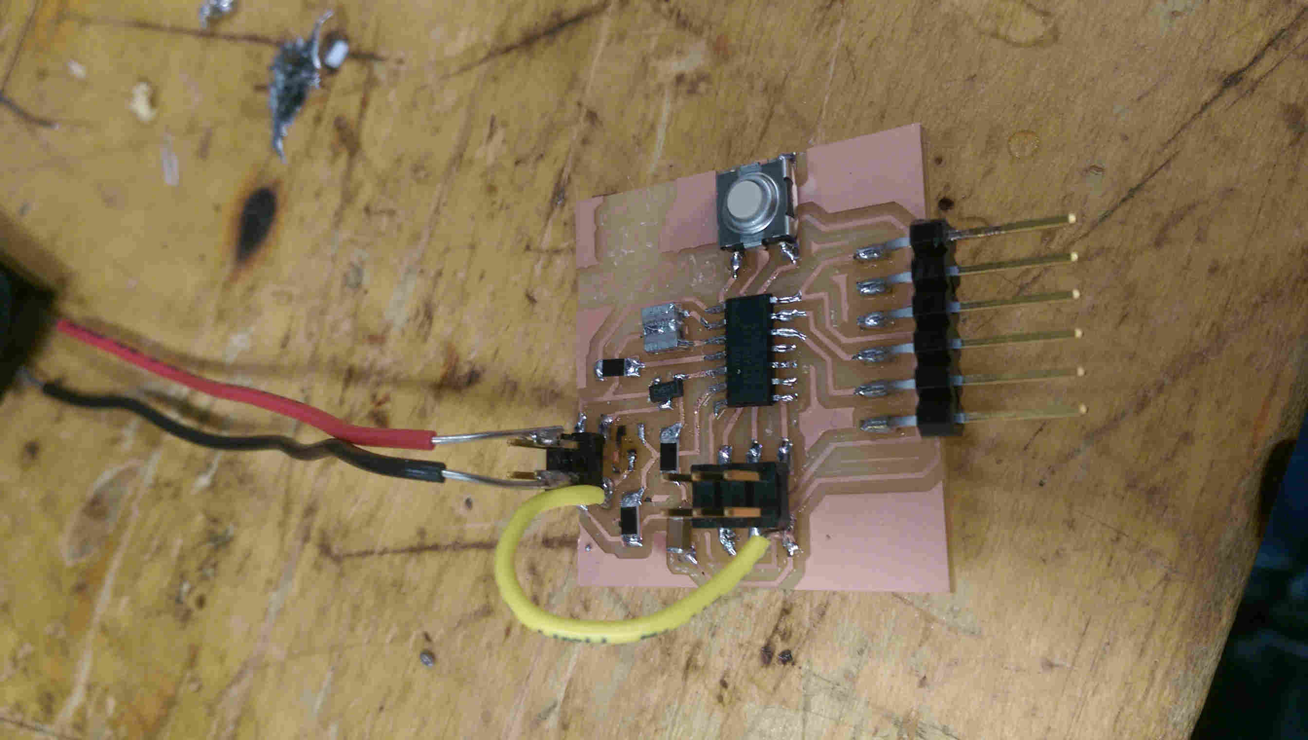
the yellow wire was added to jump +5 V to one of the speaker pinouts
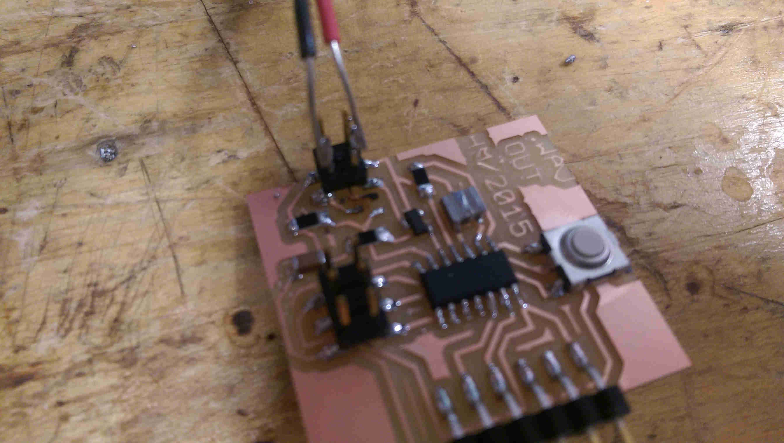
close-up view showing the pads where the transistor was fried (since removed)
down-chirp video
board design re-vamp
In order to get higher-fidelity audio output, I designed a seperate board using an H-bridge to source current to drive the speaker both ways. Topologically, this involves outputing your desired signal on one PWM output pin, and the logical inverse on another. Both of these outputs are fed as inputs to the H-bridge chip, and the H-bridge outs are then connected to the speaker pinouts.