This week for the assignment 'make something large' with for Large Format Milling, I once again ran into a familiar situation of my ambition out stripping my design ability. I guess that is partially the point of this class, to push your abilities as far as you can.
Since our stock this week was a piece 8' x 4' Oriented Strand Board (a.k.a. chip-board), a material that does not have much employ in laboratories, I again opted to make something for real life rather than lab-life
My original idea for this week was to make a modernist rocking-chair. I liked this idea (and still do), but I realized that I don't actually need a rocking-chair, and if I made a rocking-chair, I wouldn't have anywhere to put it. What I do need at my house, is a bench for our entry-way. My wife and I have a 'shoes-off' house, but we don't have anywhere to sit to take shoes on and off. I am particularly aware of this when we have guests over. Watching friends who have not mastered the 'in-step to in-step' flick off of the shoes, or have their Sambas tied 'just so' that they're effectively slip-ons, and instead seeing them lean awkwardly against the wall, or worse, sit on the floor to put on their shoes, makes me feel like a pretty crap host. We do have guest slippers, so we aren't total animals, but still we need a bench.
 At first, I had hoped to make an L-shaped bench in order to make the most of the
limited space in the entry-way. Also, since this area of the house is in a state
of perpetual cluster-f%#@ I wanted to make a combination bench/shoe-rack.
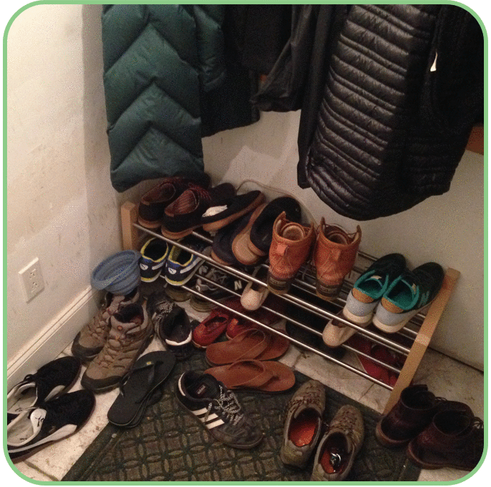
The photographic evidence clearly shows that we have over-run the standard-issue
shoe-rack that we have in this area.
At first, I had hoped to make an L-shaped bench in order to make the most of the
limited space in the entry-way. Also, since this area of the house is in a state
of perpetual cluster-f%#@ I wanted to make a combination bench/shoe-rack.
The photographic evidence clearly shows that we have over-run the standard-issue
shoe-rack that we have in this area.
Unfortunately, this is where my ambition began to outstrip my design ability. After making a few sketches of my ideas, I realized that incorporating the bend in the 'L' was going to substantially complicate the design, and if successful would only add about an extra foot of bench length. Also, I was envisioning that building the angle may require some mitre cuts, which I was not entirely sure I could do with the milling instrument. Additionally, I decided to jettison the incorporated shoe-rack for this version, and instead design it to sit over the existing shoe-rack. For starters, the version made this week would only be an initial prototype, which I would remake with 1/2" sanded plywood. I could not in good conscience have guest see a item made of chip-board be the first thing they witness as they walk into the house. So there would be an opportunity to incorporate the shoe-rack later. Second, the design of the shoe-rack would require generating a greater number of complex shapes in Autodesk Fusion360, which I am still getting the hang of, so getting the design of the bench itself would pose sufficient challenge.
I designed the bench using AutoDesk Fusion 360. Even though I planned to design the bench for press-fit assembly, and thus would comprised of primarily 2-D shapes I resisted the urge for expediency and simply design the bench as vectors in Illustrator because I know that designing and rendering in 3D, even if the fabrication is performed is a skills I need to developed. I also want to become more familiar with the parametric design capabilities in Fusion360
 While I did scale back on some of the design complexity , I still wanted to continue
the theme from week-01 to explore the technique of generating contoured surfaces
from flat stock through the use of flexures, kerfing, and selective cutting. Since
I am planning to make the final version of the bench using sanded plywood, which
supposedly can be used to form beautifully contoured surfaces using kerfing, I hoped
to incorporate an arching benchtop into the design.
While I did scale back on some of the design complexity , I still wanted to continue
the theme from week-01 to explore the technique of generating contoured surfaces
from flat stock through the use of flexures, kerfing, and selective cutting. Since
I am planning to make the final version of the bench using sanded plywood, which
supposedly can be used to form beautifully contoured surfaces using kerfing, I hoped
to incorporate an arching benchtop into the design.
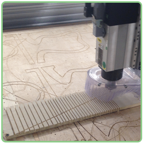
Before going too far with the design, I wanted to get some idea of the degree of curvature I could obtain in 1/2" plywood using kerfing. Of course not knowing how densely I should place kerfs along the board, I did what any good scientist would do when trying to determine the unknown value of a continuous parameter, a titration!!!
 Using a piece of scrap 1/2" plywood, I tested a series of kerfs along the board:
from 2 passes/inch, 3 passes/inch, 4 passes/inch, 5 passes/inch; with 5 inch segments
for each density. The Shopbot was fitted with a 1/8" inch endmill, and the cut depth
was set to 0.35" or ~75% of the material thickness. The cut path was set using Vcarve
software, with the tool set to move 'On' the vector path (as opposed to 'Inside' or
'Outside' the path).
Using a piece of scrap 1/2" plywood, I tested a series of kerfs along the board:
from 2 passes/inch, 3 passes/inch, 4 passes/inch, 5 passes/inch; with 5 inch segments
for each density. The Shopbot was fitted with a 1/8" inch endmill, and the cut depth
was set to 0.35" or ~75% of the material thickness. The cut path was set using Vcarve
software, with the tool set to move 'On' the vector path (as opposed to 'Inside' or
'Outside' the path).
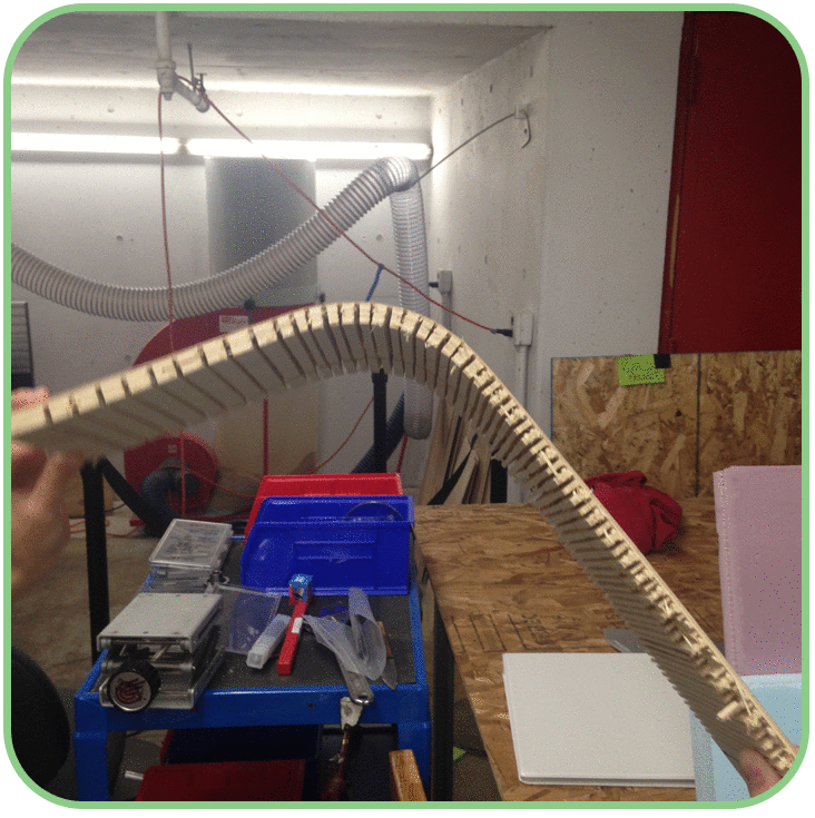
3 passes/inch was clearly the optimal density for kerfing for 1/2" plywood, achieving remarkable bend of almost 90-degrees over the fairly short distance of 5". Interestingly both the less dense condition of 2 passes/inch and higher densities of 4 and 5 passes/inch left the board rigid.
This exercise taught me a few lessons:
- - When kerfing plywood, try to set the cut depth so as to leave the last layer of veneer
- - Vcarve does not like 'Open' Vectors, i.e. it is happy to set a tool path for
a square or a circle, but not a line segment.
Therefore, when setting up kerfing it is better to set the kerfs as a series of boxes rather than a series of line segments - - It is more difficult to set the tooling for the cut to go all the way to the
edge of the board. Also, when cutting to the edge
of the board, it is not possible to tack the broad down to the cutting surface along that edge. As the kerfing progresses,
the board will become flexible and affect the accuracy of cutting depth. Instead, it appears better to set
the kerfing to occur in the interior of the work-piece, and then cut the kerf segment to the desired dimension
with through-cuts in a second pass.


