The assignment this week was to reproduce the Fab Lab 'Hello World' circuit board with some modification on the basic design. Since I'm fairly new to circuit board fabrication, and have to get my board from week 2 to be fully functional, I decided try and keep it simple for this week.
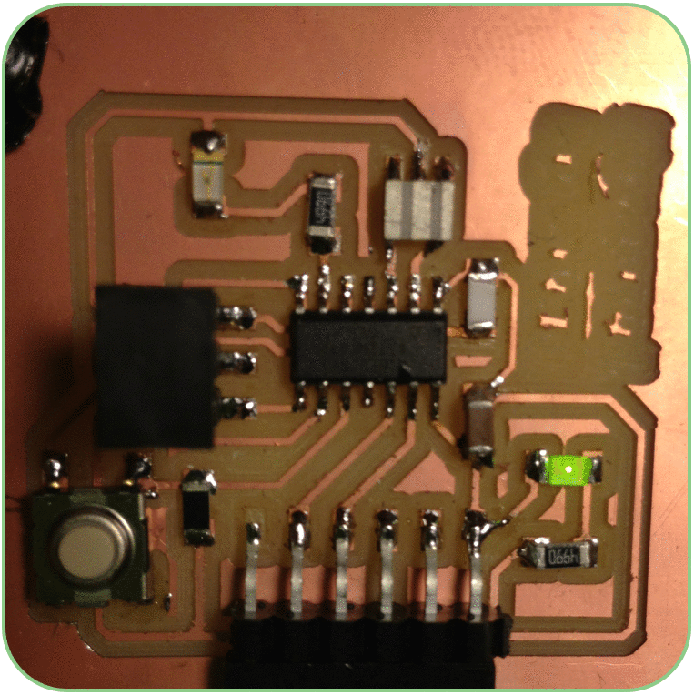
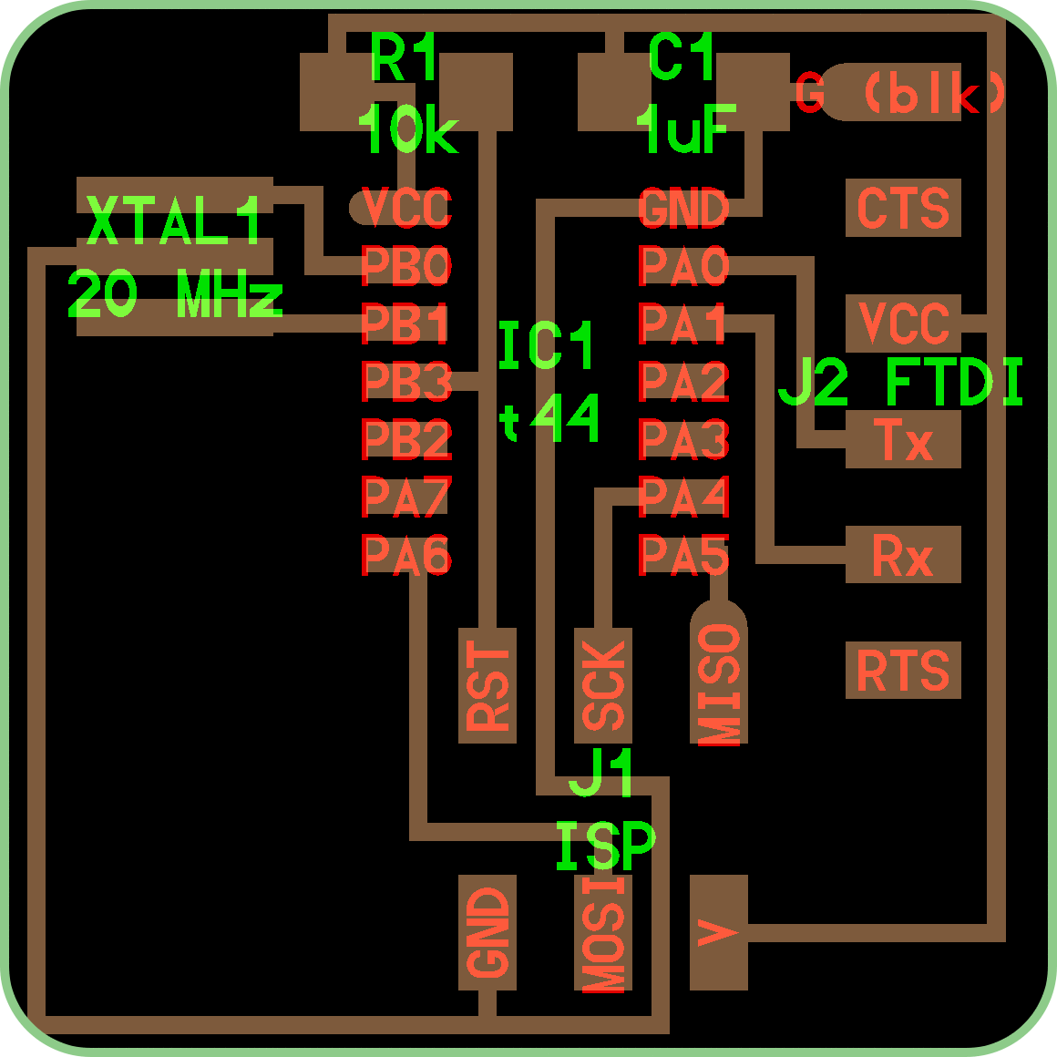 The base 'Hello World' board consists of a ATTINY44 micro-controller, a 6-pin FTDI
header for powering the board, a 6-pin header for programming the board, a 10K Ohm
pull-up resistor connected to the micro-controller, and a 1µF cross-over capacitor.
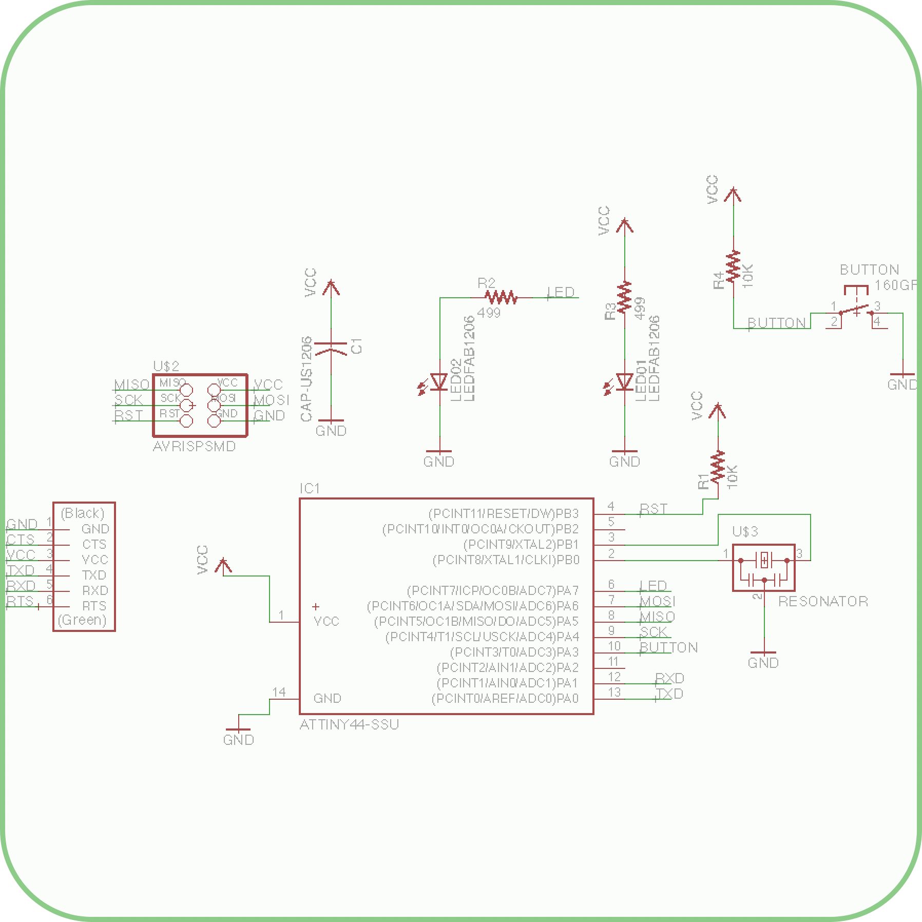
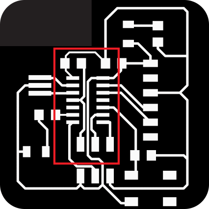
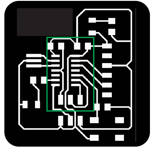
Following an example tutorial posted by Anna Kaziunas France from the AS220 Fab Lab in Providence RI, I modified the board by adding a LED (and necessary current limiting resistor) to pin PA7 of the micro-controller, and a button (with resistor in parallel) to pin PA3. If my understanding of the micro-controller is correct, this configuration will allow for generating two 'states' at pin PA3, one when the button is pressed and another when it is not, and these states can be reported by different blinking patterns expressed by the LED connected to pin PA7.
A second modification that I incorporated into the board, was a quality control measure recommended by TA Palash Nandy. This consisted of a second circuit in parallel, with a LED and current limiting resistor, acting as an 'On' light for the board. When power is supplied to the board, this LED will light, providing assurance the the board is receiving power.
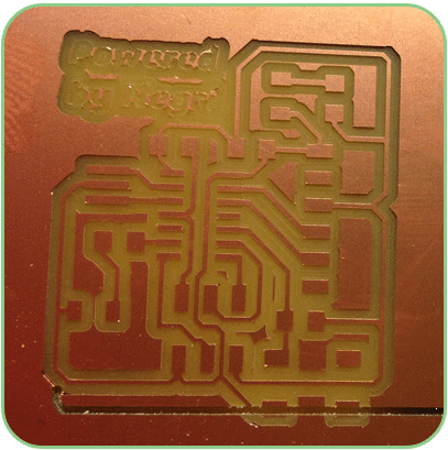
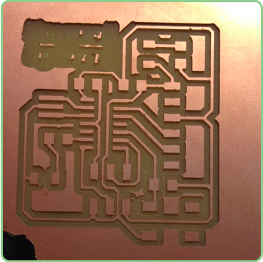
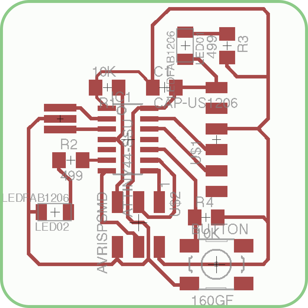
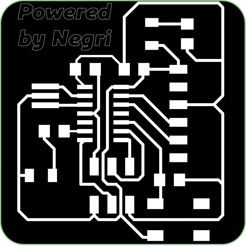
Following Anna's tutorial and using Eagle PCB design sortware, I was able to layout the schematic of the board, and render the traces. After exporting the traces as a .png file (in monochrome! important), I was able to add some personalization in Photoshop. Who needs 'Intel Inside', when you are Powered by Negri! Now it was time to set tool-paths and start milling.
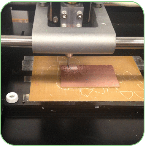 Time to mill. I secured the board stock to the milling surface, loaded the 1/64th" end-mill, set
the X,Y,Z min, and off we go! Unfortunately, I ran into another set back, during the
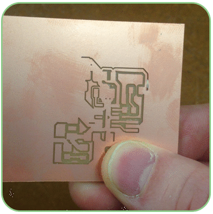
milling the board came loose from the milling surface, and the end-mill started moving the
board around rather than cutting traces over it. No worries, new board, extra-tape this time
to make sure the board is really secure, set the X,Y,Z and off we go again.
The second time around the board stayed in place, and traces were all milled cleanly.
