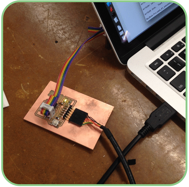
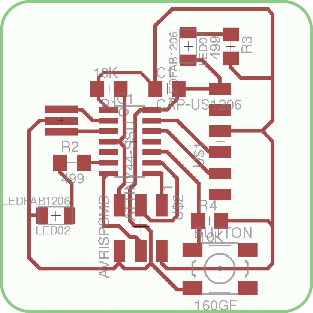
This week, the goal was to embed a program on the modified 'Hello World' circuit board that I made back in week 5. At that time, I made the board following the tutorial posted by Anna Kaziunas France from the AS220 Fab Lab in Providence RI, to an LED and a button into the board. I also incorporated a parallel circuit onto the board with a single green LED to act as a 'Power On' indicator.
 Once again, I realized what a complete newbie that I am to embedded programming (and
electronics in general), but thankfully Rob Hart recommended a great book for getting
started with AVR devices, Make: AVR Programming by Eliot Williams. The first
couple of chapters were great for getting my bearings on this process. Unfortunately,
I only had enough time this week to begin going through this book, but I think it will
be an invaluable asset going forward.
Once again, I realized what a complete newbie that I am to embedded programming (and
electronics in general), but thankfully Rob Hart recommended a great book for getting
started with AVR devices, Make: AVR Programming by Eliot Williams. The first
couple of chapters were great for getting my bearings on this process. Unfortunately,
I only had enough time this week to begin going through this book, but I think it will
be an invaluable asset going forward.
 The first order of business for the project was to write ( in reality, slightly
edit ) a program in C-code to inform the processor what I want it to do. My board
has 1 LED (aside from the power indicator) and 1 Button, so it is pretty limited
in what I am going to be able to make it do, and will probably involve something like
press the button, and make the LED turn on, but I was still completely out
of my depth. Once again, Rob Hart come through by posting a tutorial on the class site
with sample C-code and a make file for a simple push button/light comes on
device such as my board. Following Rob's code, I was able to make slight edits
to make it work with my board.
The first order of business for the project was to write ( in reality, slightly
edit ) a program in C-code to inform the processor what I want it to do. My board
has 1 LED (aside from the power indicator) and 1 Button, so it is pretty limited
in what I am going to be able to make it do, and will probably involve something like
press the button, and make the LED turn on, but I was still completely out
of my depth. Once again, Rob Hart come through by posting a tutorial on the class site
with sample C-code and a make file for a simple push button/light comes on
device such as my board. Following Rob's code, I was able to make slight edits
to make it work with my board.
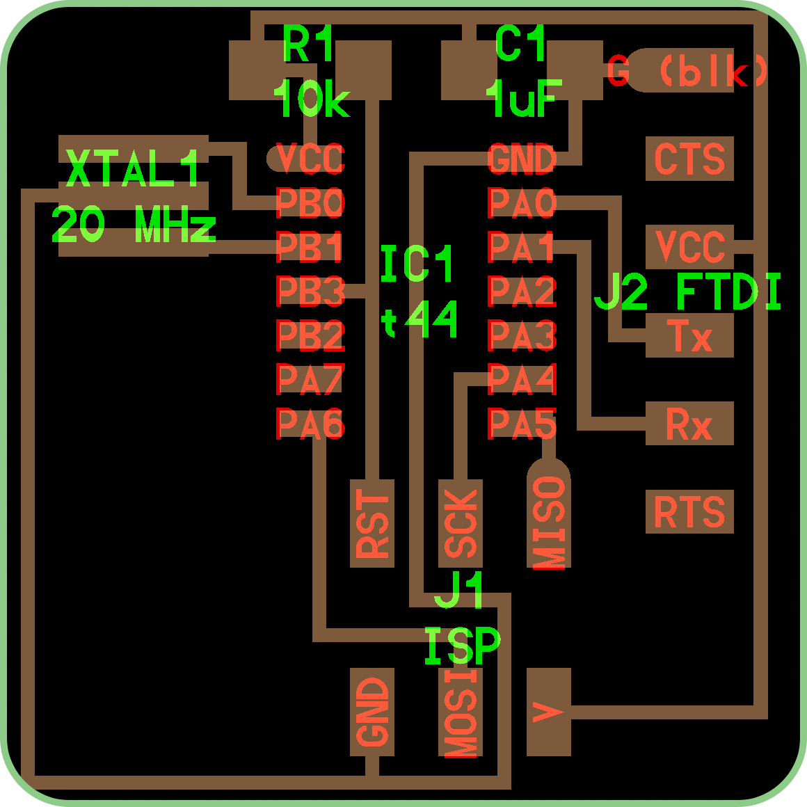
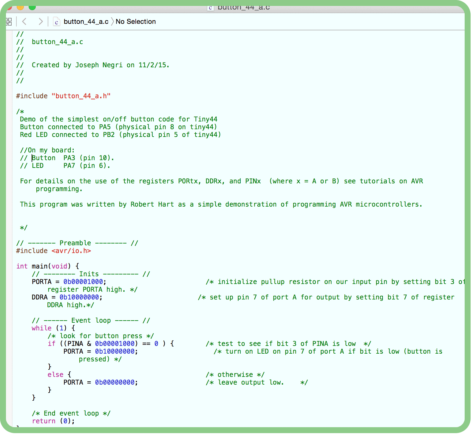 From following Rob's code, I learned my 1st Big Lesson of the Week:
Know what you want your board to do before you design it. Because I was somewhat
blindly following the tutorial when building the board, I was not giving that much
consideration to what it would be doing, or how it would be programmed, I did not give much
thought to which pins should be connected to which peripherals. So instead of utilizing the different
banks of pins (A & B) on the Attiny44 chip, the board as I made it had connected both
components to A pins (Button to pin PA3, and LED to pin PA7). While this did not prevent
me from being able to program the board, it did make it more confusing when assigning
pin registers in the C-code. It would have made more sense to have the button to an
'A' pin (such as PA3), and the LED to a 'B' pin (such as PB2), so that it would have been
more straight forward to assign the pin registers as 'A' for inputs, and 'B' for outputs.
From Rob's code, I was able change which pins should be High (1) and which pins should be
Low (0) for the conditions in the program. Which brought me to the 2nd
Big Lesson of the Week When counting pins within the pin registers,
count from the Right and remember that pins are zero indexed.
From following Rob's code, I learned my 1st Big Lesson of the Week:
Know what you want your board to do before you design it. Because I was somewhat
blindly following the tutorial when building the board, I was not giving that much
consideration to what it would be doing, or how it would be programmed, I did not give much
thought to which pins should be connected to which peripherals. So instead of utilizing the different
banks of pins (A & B) on the Attiny44 chip, the board as I made it had connected both
components to A pins (Button to pin PA3, and LED to pin PA7). While this did not prevent
me from being able to program the board, it did make it more confusing when assigning
pin registers in the C-code. It would have made more sense to have the button to an
'A' pin (such as PA3), and the LED to a 'B' pin (such as PB2), so that it would have been
more straight forward to assign the pin registers as 'A' for inputs, and 'B' for outputs.
From Rob's code, I was able change which pins should be High (1) and which pins should be
Low (0) for the conditions in the program. Which brought me to the 2nd
Big Lesson of the Week When counting pins within the pin registers,
count from the Right and remember that pins are zero indexed.
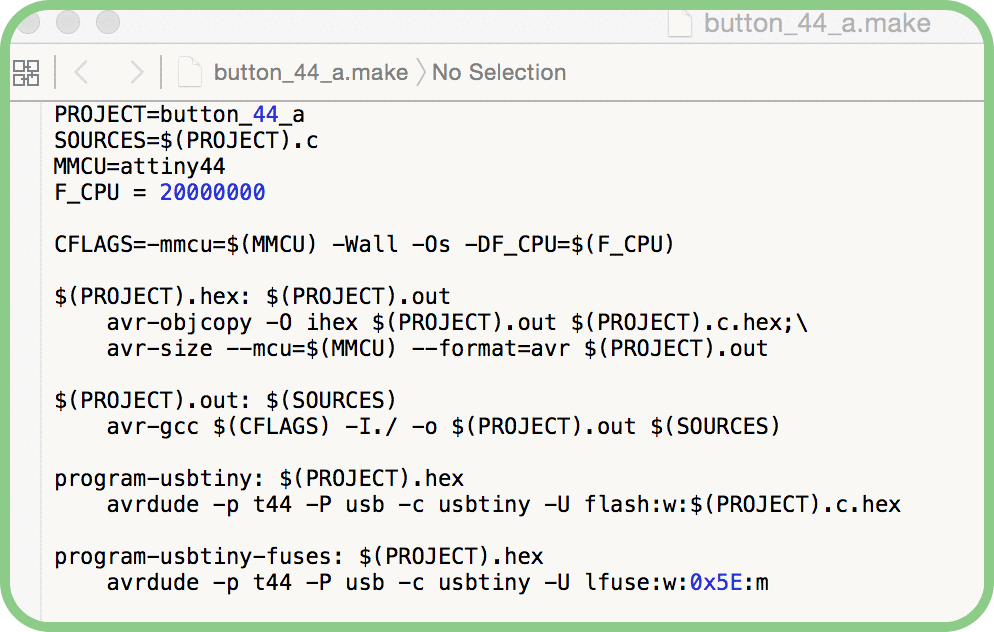 Reading through Rob's make-file, I was able to get the jest of what it says, with the
'Project' being the C-code program, the 'MMCU' being the chip to program, an attiny44, and
'F_CPU' being the clock speed 20MHz. With the following commands for compiling the code
using GCC and for writing to the board using the AVRDUDE programmer.
Reading through Rob's make-file, I was able to get the jest of what it says, with the
'Project' being the C-code program, the 'MMCU' being the chip to program, an attiny44, and
'F_CPU' being the clock speed 20MHz. With the following commands for compiling the code
using GCC and for writing to the board using the AVRDUDE programmer.
Time to program the board!!! With a lot of help from Dan Chen and following the tutorial on maxembedded.com for setting up the AVR-GCC Toolchain on Mac OSX, I was able to install AVR-GCC and AVRDUDE. Then within the terminal, I navigated to the directory containing the C-code program 'button_44_a' and the Make-file and said the 3 magic words (phrases really) of AVR Programming:
- sudo make -f button_44_a.make
- sudo make -f button_44_a.make program-usbtiny-fuses
- sudo make -f button_44_a.make program-usbtiny
Thankfully, the programming executed without error, and more importantly, when I pressed the button the red light came on!!! Success! While it may seem an underwhelming result, but I know how it happened. I started looking into how I could use the Arduino IDE to generate this program, but I did not get very far down that road, so something to do next week.