Press-pin connector for in-system programming.

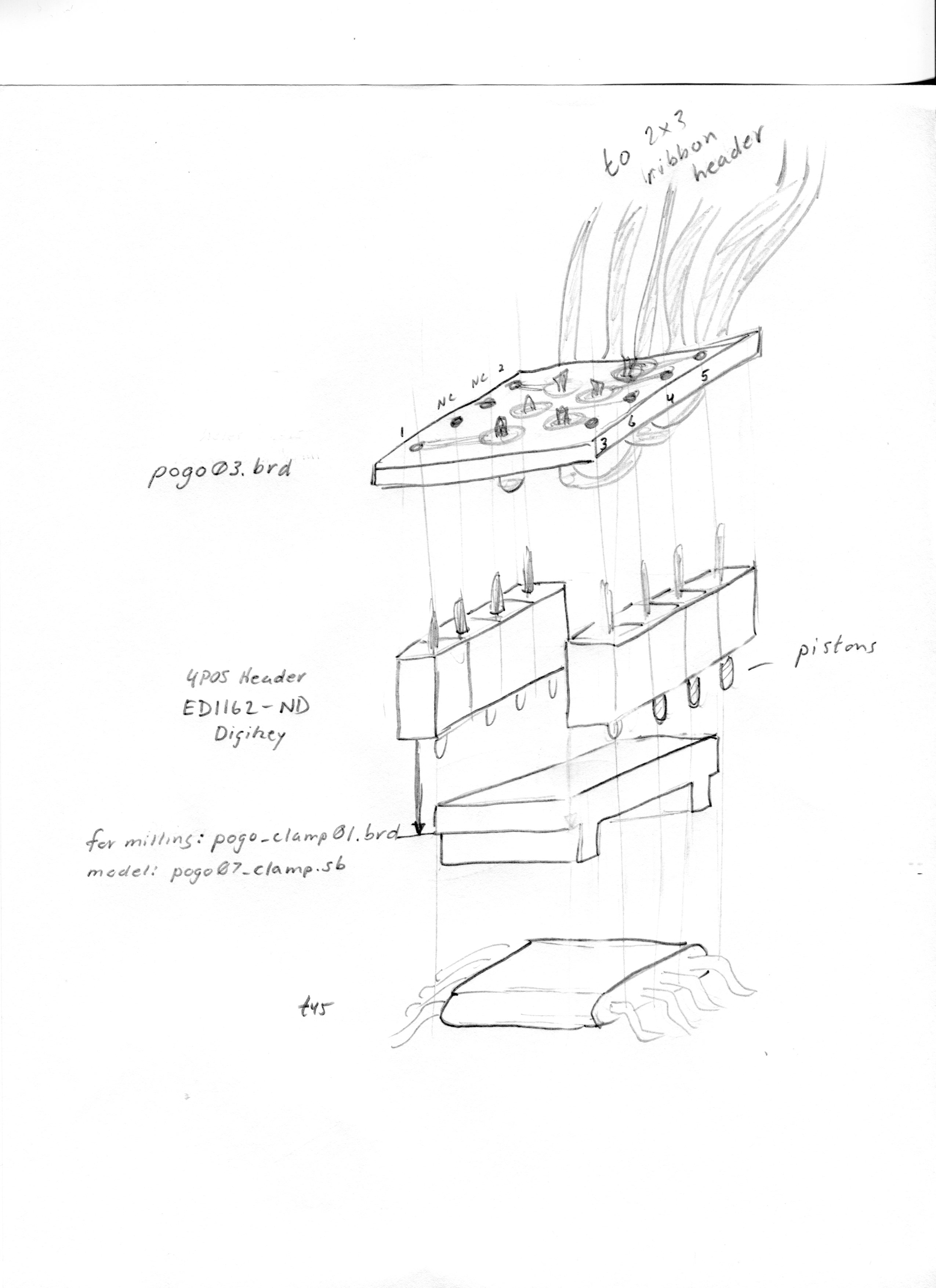
Connector using "pogo" pins to contact legs of tiny45 (and tiny44 in modified design) so that ISP 2x3 header is not required.

First iteration

Below is the first iteration, in which premade four-pin headers are used for the pin contacts, and ribbon cable wires are soldered individually into holes in an upper circuit board. This design works well, but presents many problems in contruction, since ribbon wires are difficult to solder onto the board. Drawings and files are below for this iteration.

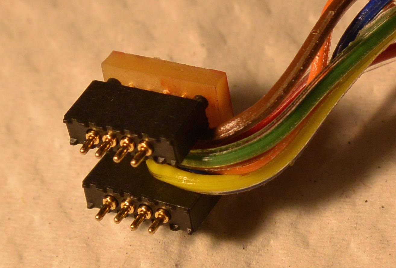
This is the top board and attached headers. Clamp is not shown, but will be glued between the headers.

  • Top circuit board. Eagle File: pogo03.brd Solder ribbon cable wires into ~0.03" holes, which can be drilled with 1/32" endmill. Drill holes for pins with #78 drill = .0156". Cannot drill hole through circuit board with our 1/64" endmills, but can use them to locate the holes by removing the copper layer.
  • Header pins. Digikey ED1162-ND. Solder into top board after ribbon wires attached.
  • Clamp. Antimony file. is a 3D model. Eagle board. This board file has the outlines for milling the clamp. I used 0.133" phenolic (garolite) from McMaster Carr. Nominally 0.125" : McMaster part 6842K61. Equivalent to this would be two FR1 boards, laminated with epoxy. For milling, depth of "legs" is 1.66 mm. Overall depth is 0.133" = 3.3 mm.
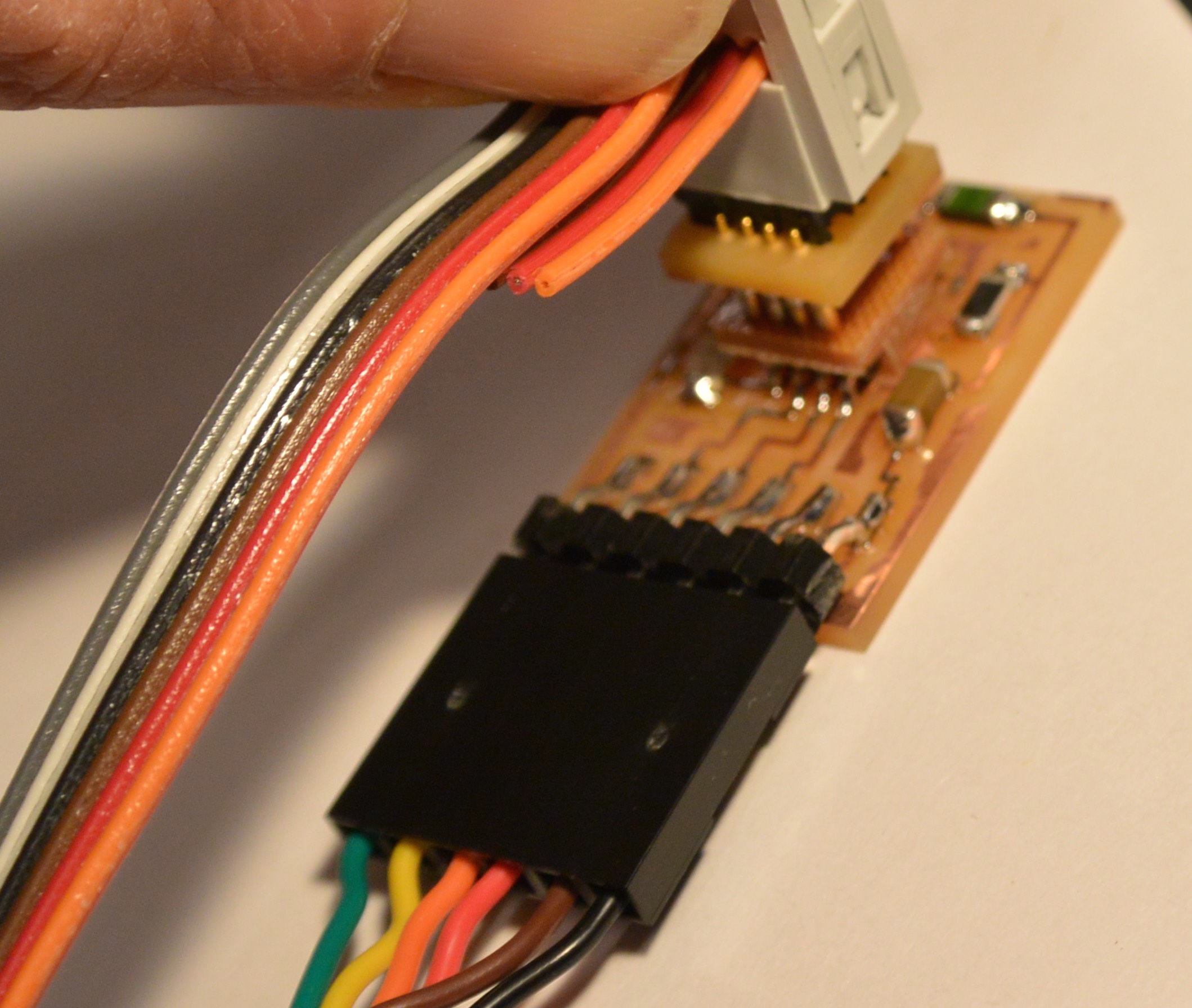
  • This connector works for programming the tiny45. It takes some care to locate, and needs to be held in place while programming. It may need an extender to make it easier to push onto board.