The FabTinyStar is yet another version of an AVR ISP programmer/board that can be produced in a fab lab using a milled PCB and readily available components. The project is based on the efforts of many people. For more history of the FabTinyStar and the people who have contributed to it, please refer to Zaerc's FabTinyStar page.
This version (the "FabTinyISP Minimal" is a minor revision to Zaerc's version 0.3 (Bas), with small modifications:
This page describes how to build, program, test, and debug the board.
One possible point of confusion in this document is that the device you're building will become an AVR programmer, but you also need a working AVR programmer in the process of building it. Your board refers to the new programmer that you are building. Programmer refers to the working programmer that you'll use to initialize yours. At the end of this document, your board becomes a programmer.
The FabTinyISP is a "low-speed" USB 1.1 device. This is the slowest (and one of the oldest) of the USB device types. Typically used for mice and keyboards, low-speed devices operate at 1.5MHz and have much less strict timing requirements, which enables a purely software-based implementation of the USB protocol to be used (the ATtiny45 does not have hardware USB capability).
While all later USB versions should be backwards-compatible with older devices like the FabTinyISP, there are a few things to keep in mind to avoid issues:
Download the PNG files for the traces and the board outline:
The Altium source files are available here if you want to modify the design.
Since there are different processes for milling on different machines, this is not described here. Please refer to a PCB milling reference that's applicable to the equipment in your shop.
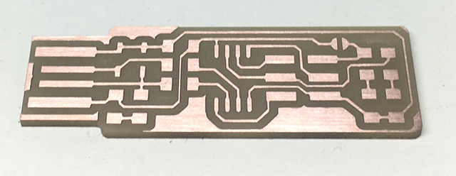
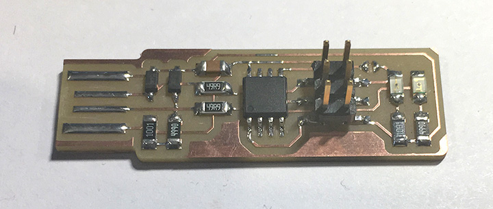
The finished PCB should look something like this:
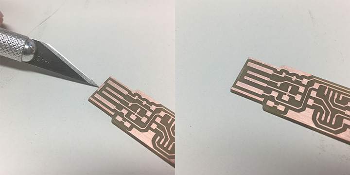
Depending on the number of offsets you milled, there might be a tiny bit of copper left at the edge of the board in front of the USB contacts. 5 offsets should be sufficient to remove all of the copper in the milling process, but takes a bit longer to mill. If you milled fewer offsets (I did 3 in the above photo), the extra copper can be removed with a knife. Only the copper in front of the pads needs to be removed; the copper left on the sides is fine.
Obtain the components:
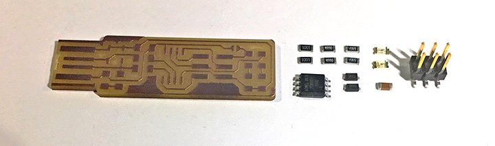
The LEDs and their associated resistors are optional; the red LED lights when the target circuit is powered, and the green LED lights when the programmer is talking to the target.
Solder the parts to the PCB, using the schematic and board image below as a reference for component values and placement. Start with the most difficult parts (the ATtiny45) first, so you have the most access. Install the ISP header last, as it is large and can get in your way if you do it earlier.
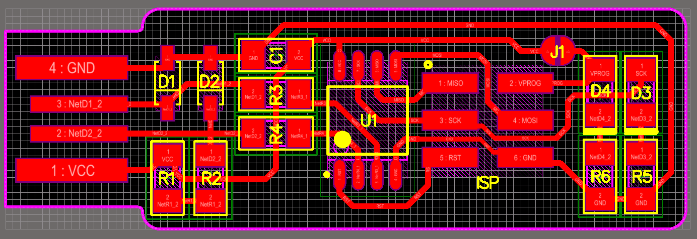
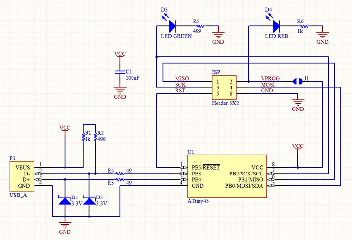
Note the components that must be installed in the correct orientation:
Use solder to create a bridge on the jumper near the ISP header (J1). This temporarily connects VCC to the Vprog pin on the ISP header so that the header can be used to program the tiny45. (The programmee supplies voltage on this pin and the programmer detects it). Once it's programmed, we'll remove this bridge to turn the board into the programmer rather than the programmee.
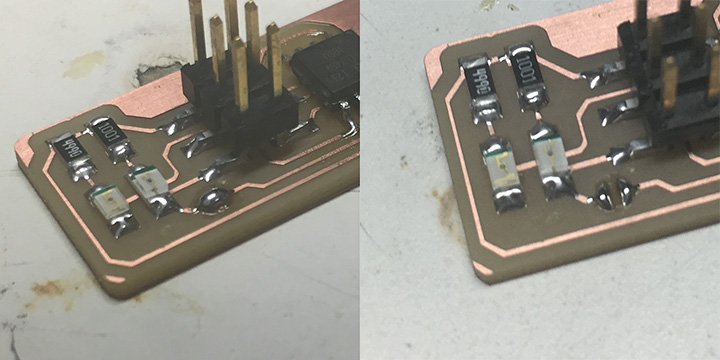
The solder jumper, bridged and not.
The PCB ends up just slightly thin to work well in most ports. To ensure a good USB connection, I recommend the following one or two improvements.
First, flow some solder onto the USB contacts on the board to build them up a little bit. Heat the pad and apply solder, moving the iron tip along the pad to distribute it. Once you have enough solder, wipe the iron tip across the pad in one continuous motion to even it out into a smooth layer. If you don't get a smooth layer, you need more flux: clean off your iron tip on the sponge, apply a little more solder to the pad, and wipe across it again. Excess solder will come away on the iron tip. (See the above image of the finished programmer for how the USB pads should look).
Doing the above is sufficient most of the time, but I still like to add a little more thickness by gluing some extra material to the bottom of the PCB. A small scrap of plastic clamshell packaging works well. I use a tiny drop of CA glue to affix a small piece to the bottom of the USB connector area, then trim the excess plastic once it's set. (Do be careful not to get superglue on the rest of the board, especially the USB contacts on the other side).
While it may seem early to start debugging already (we haven't even tried anything yet!) it is always prudent to check your work before plugging in a board. It only takes a couple of minutes and can save you headaches down the road.
Before you can build and program the firmware onto your board, you need to set up your development environment. You'll use this setup for all of your AVR programming for the class. The setup differs a bit for each platform, but once the software is installed it should work more or less the same on each platform.
You'll be using a command line shell (bash) in your platform's terminal to execute all of the commands below. If you are unfamiliar with using the command line, you may want to review a tutorial.
For Ubuntu and other Debian-based distributions, enter the following command, followed by your password when prompted:
sudo apt install avrdude gcc-avr avr-libc make
Download and install CrossPack.
Installing the toolchain on Windows is slightly more complicated. Separate instructions are provided here.
Download the firmware source code and extract the zip file (on Linux, unzip fts_firmware_bdm_v1.zip). Open your terminal program and cd into the source code directory.
Run make. This will build the hex file that will get programmed onto the ATtiny45. When the command completes, you should now have a file called fts_firmware.hex. If the command doesn't complete successfully, something is wrong with your toolchain installation. Consult the error messages for information that will help you debug it.
First, update the Makefile for the type of programmer you're going to use to program your board. The Makefile, by default, assumes that you're going to use a programmer in the usbtiny family (e.g. another FabISP board). If you're using a different programmer, first figure out what avrdude (the programming software) calls it. Here are some commonly found AVR programmers:
Edit the file called Makefile. It is important to use a text editor intended for programmers; programs like Notepad or WordPad can add formatting information that breaks the file. On Linux, gedit (GUI) or nano (command line) are good options; Windows users might want to use Notepad++. TextEdit on OS X usually works, just make sure you save as plain text and not RTF (and make sure no ".txt" gets added to the filename). Sublime Text is another popular choice on several platforms. In general whatever you use to edit your HTML code is probably an okay choice.
Near the top of the file, find the line that says:
PROGRAMMER ?= usbtiny
and change usbtiny to whatever programmer you're using.
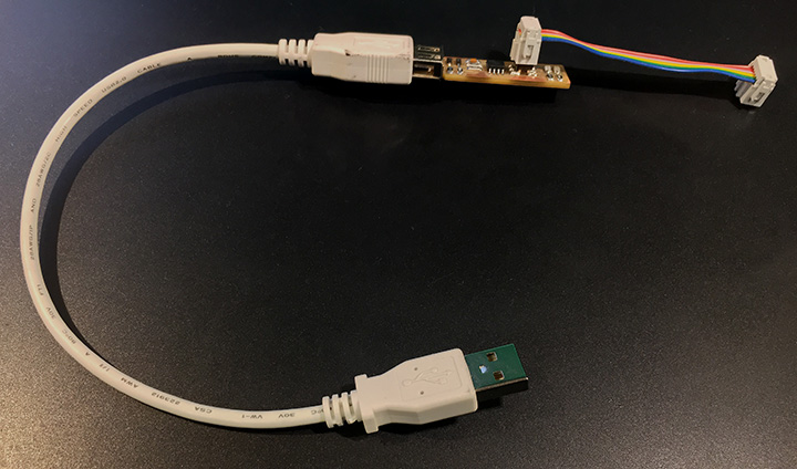
Go ahead and plug the board into a USB port. Use a USB 2.0 port, rather than a USB 3.0 port, if you have one. It is also recommended to use a short USB extension cable or a USB 2.0 hub rather than plugging directly into the port, especially if your USB ports are upside down. This will remove the strain from and reduce the risk of damage to your built-in USB ports. For example:
If you installed the red LED, it should be lit up now. If not, check the solder jumper and make sure that it is bridged. If your computer complains about a USB device drawing too much power, unplug the board and check for shorts.
Connect the programmer to the ISP header on your board. Note that there are two different orientations in which you can connect the cable; it is imporatant that you get pin 1 in the right place. Pin 1 is marked in the board diagram with a dot and has the MISO signal connected to it. If you look at the plastic connector on the programmer cable, there should be a small arrow, dot, or manufacturer's name marking the corner with pin 1. Note that there's no enforced standard for which direction the cable comes out of the connector, so look for the pin 1 marker.
Run make flash. This will erase the target chip, and program its flash memory with the contents of the .hex file you built before. You should see several progress bars while avrdude erases, programs, and verifies the chip.
If something went wrong, check:
If you've checked all of the above and still can't program your board, use a multimeter to verify that there is continuity between the pins on the chip and the ISP header, and that there isn't continuity where there shouldn't be (shorts between adjacent pins or traces).
Once you've succesfully programmed the flash memory, it's time to set the configuration fuses. We'll do this in stages:
Run the make fuses command. This will set up all of the fuses except the one that disables the reset pin. Again, you should see several progress bars from avrdude. If this step fails but the previous one worked, you likely have an intermittent connection somewhere.
Now we'll check to make sure that the USB on your board works, before blowing the fuse that will enable it as a programmer. Unplug your board from the USB port and disconnect the programmer, then plug it back in to the USB. Make sure the programmer you used to program your board is also disconnected from the computer.
Type lsusb in the terminal, which will list USB devices. If you see a "Multiple Vendors USBtiny" device, it worked! If it didn't, the dmesg command might provide more info on what went wrong. You want to see a message about a "New low-speed USB device" without any further errors. (Note that sudo dmesg -c will clear the messages after printing them out, which is useful to do before plugging in your board so you'll be able to tell exactly which messages are a result of plugging it in). If you don't see the "new low-speed device" message, check the pull-up on the USB line (the 1kΩ and 499Ω resistors, R1 and R2, in series between VCC and D-) for correct values and good connectiions (the computer uses these resistors and their values to detect what type of USB device has been connected). If you do see the "new low-speed device" message, but there are other errors after, try the following:
Open Apple System Profiler (Apple Menu → About this Mac → More Information; or from the Utilities folder). Select USB from the list on the left, and you should see the USBTiny listed as a device on the right. If it shows up, it is working properly. Otherwise, follow the debugging instructions above (note that MacOS does not have a dmesg command, though similar information might be available somewhere in the Console app). Either check everything above, or plug into a Linux machine to see whether or not you get the "new low-speed device" message in dmesg.
Windows lists USB devices in Device Manager (Start → Control Panel → System → Device Manager), though it doesn't always tell you what they are until the correct drivers are installed. USB devices may also appear in "Devices and Printers" or "Hardware and Sound". If you don't know your Windows machine well enough to find whether or not the USBtiny device is showing up, you might want to plug into someone's Linux machine or Mac to check for sure whether it's working.
Congratulations, you're almost to a working programmer. The ATtiny45 on the board has the code loaded onto it and is working correctly if you've made it this far. There are two final steps left to turn your board into a programmer that can program other boards.
First, we need to change the bit that will turn the ATtiny45's reset pin into a GPIO pin. Once again, this will disable our ability to reprogram this ATtiny45 in the future, which is why we wanted to make sure everything was working before doing this. Connect your ISP programmer to your board one more time, and run make rstdisbl. This does the same thing as the make fuses command, but this time it's going to include that reset disable bit as well. You should see some progress bars, and with that, avrdude will never be able to talk to this chip again through the ISP header.
Second, we need to disconnect VCC from the Vprog pin on the ISP header by removing the bridge on the solder jumper. Sometimes the excess solder will stick to a clean soldering iron tip; if not, use desoldering braid to remove the solder from the jumper, thus breaking the connection.
You should now have your very own working ISP programmer! But, before you call it a day, use your board to try programming another board.

This
work is licensed under a Creative Commons
Attribution-NonCommercial-ShareAlike 4.0 International License.